Jaw Sort Coupling Choice Process
The variety procedure for determining the correct jaw coupling dimension and elastomer demands utilizing the charts shown to the following pages. You will find 3 parts to be picked, two hubs and one elastomer. Once the shaft size on the driver and driven from the application are from the same diameter, the hubs chosen will likely be the exact same. When shaft diameters differ, hubs picked will vary accordingly.
Facts necessary before a coupling could be picked:
HP (or KW) and RPM or Torque 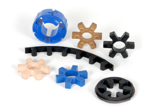 of driver
Shaft sizes of driver and driven products and corresponding keyways
Application description
Environmental disorders (i.e. extreme temperature, corrosive conditions, area limitations)
Ways In Choosing A Jaw Coupling
Phase 1: Identify the Nominal Torque of the application by utilizing the next formula:
Nominal Torque = in-lb = (HP x 63025)/RPM
Nm = (KW x 9550)/RPM
Stage two: Employing the Application Service Elements Chart 1 decide on the service factor which greatest corresponds for your application.
Stage 3: Determine the Design Torque of your application by multiplying the Nominal Torque calculated in Phase 1 from the Application Support Aspect determined in Phase two.
Style Torque = Nominal Torque x Application Services Aspect
Step four: Using the Spider Performance Information Chart 2, select the elastomer materials which very best corresponds to your application.
Phase 5: Employing the Jaw Nominal Rated Torque Chart 3 , find the acceptable elastomer material column to the elastomer selected in Phase four.
Scan down this column to the very first entry the place the Torque Value during the appropriate column is higher than or equal towards the Style and design Torque calculated in Phase three.
Once this value is located, refer to the corresponding coupling dimension during the to start with column with the Jaw Nominal Rated Torque Chart three .
Refer towards the optimum RPM worth for this elastomer torque capability to make sure that the application needs are met. If your necessity is not really pleased at this point, yet another sort of coupling may be expected to the application. Please consult Lovejoy engineering for support.
Phase 6: Review the application driver/driven shaft sizes on the greatest bore size obtainable over the coupling selected. If coupling bore size is not really big ample for your shaft diameter, pick the next biggest coupling that should accommodate the driver/driven shaft diameters.
Phase 7: Working with the UPC number assortment table , find the suitable Bore and Keyway sizes required and locate the amount.