Product Description
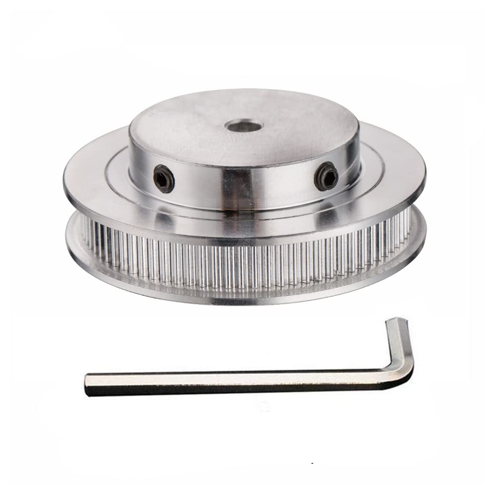
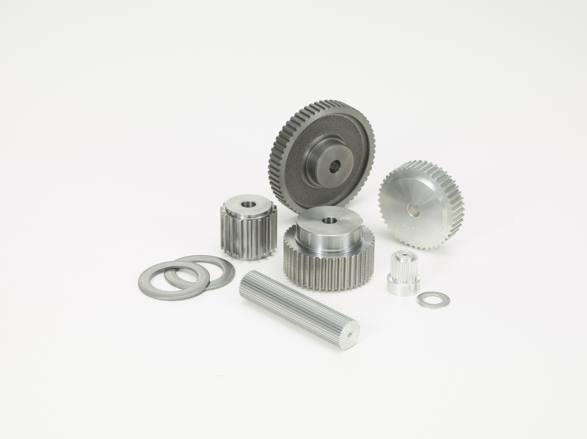
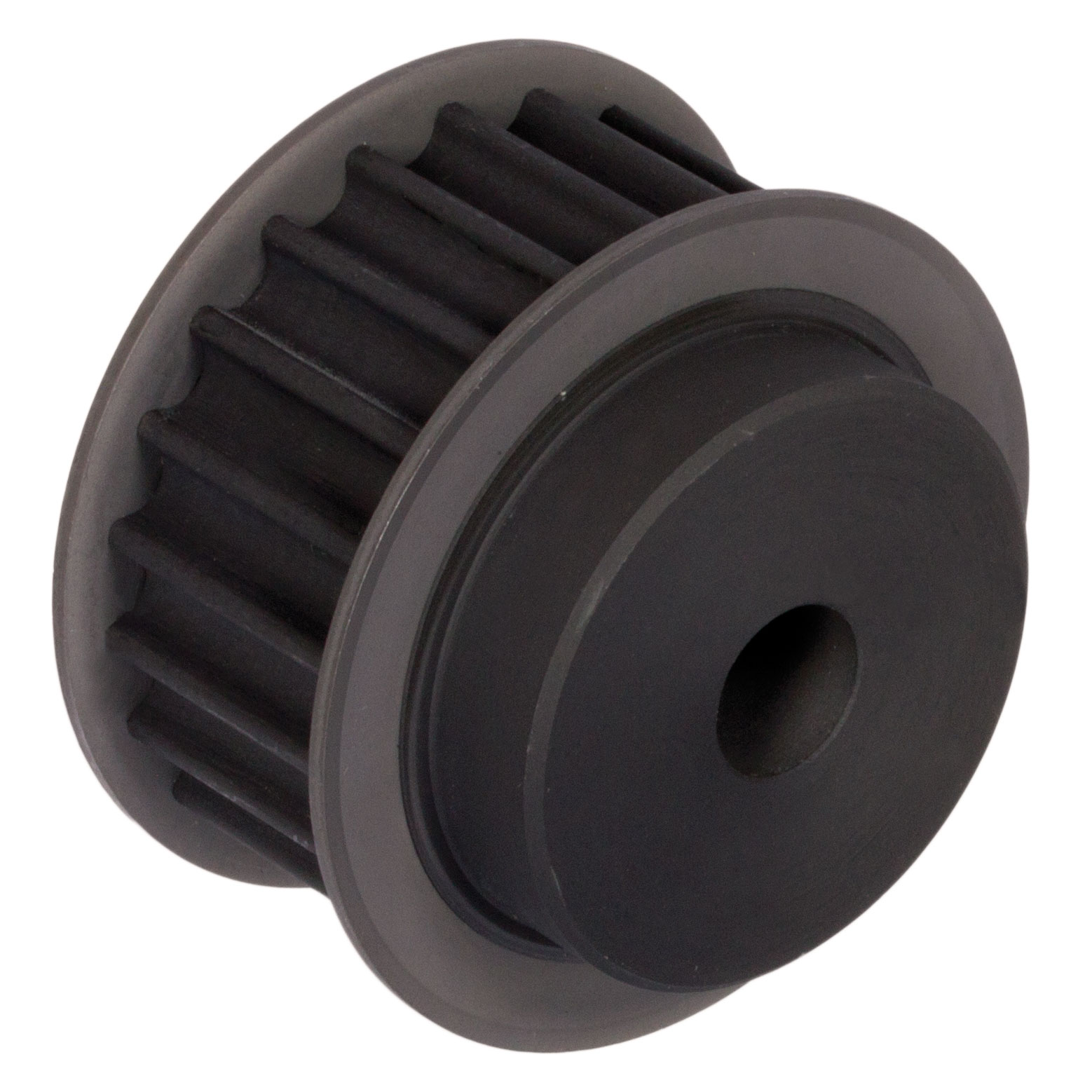
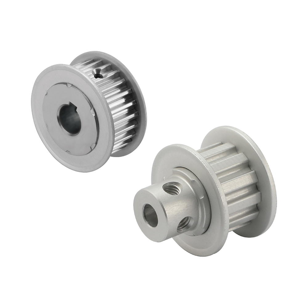
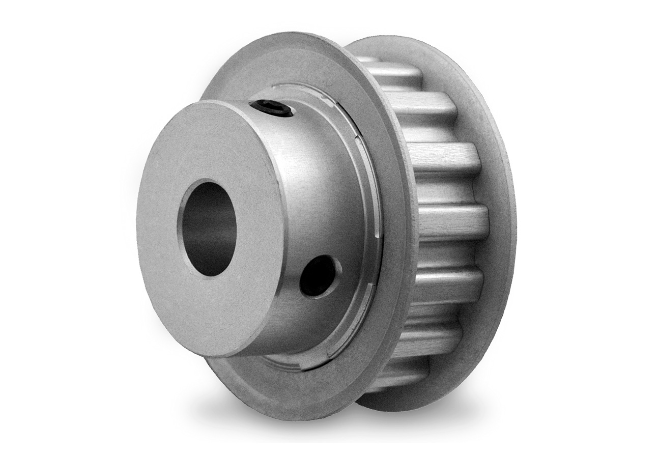
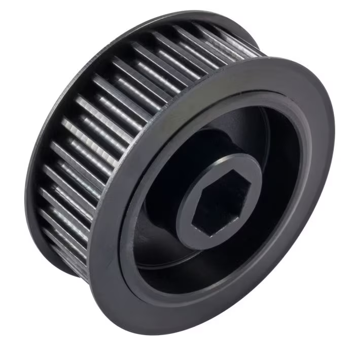
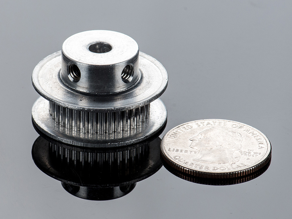
CHINAMFG Machinery offers a wide range of high quality Timing Belt Pulleys and Toothed Bars/ Timing Bars. Standard and non-standard pulleys according to drawings are available.
Types of material:
1. AlCuMgPb 6061 6082 Aluminum Timing Pulley
2. C45E 1045 S45C Carbon Steel Timing Pulley
3. GG25 HT250 Cast Iron Timing Pulley
4. SUS303 SUS304 AISI431 Stainless Steel Timing Pulley
5. Other material on demand, such as cooper, bronze and plastic
Types of surface treatment
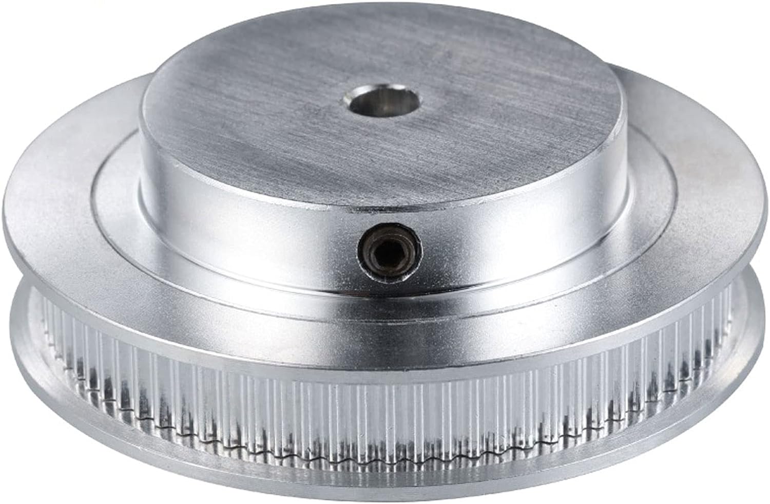
1. Anodized surface -Aluminum Pulleys
2. Hard anodized surface — Aluminum Pulleys
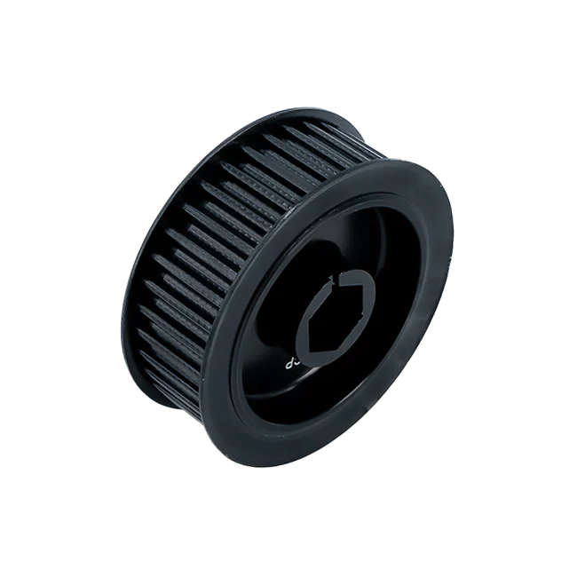
3. Black Oxidized surface — Steel Pulleys
4. Zinc plated surface — Steel Pulleys
5. Chromate surface — Steel Pulleys; Cast Iron Pulleys
6. Nickel plated surface –Steel Pulleys; Cast Iron Pulleys
Types of teeth profile
| Teeth Profile | Pitch |
| HTD | 3M,5M,8M,14M,20M |
| AT | AT5,AT10,AT20 |
| T | T2.5,T5,T10 |
| MXL | 0.08″(2.032MM) |
| XL | 1/5″(5.08MM) |
| L | 3/8″(9.525MM) |
| H | 1/2″(12.7MM) |
| XH | 7/8″(22.225MM) |
| XXH | 1 1/4″(31.75MM) |
| STS STPD | S2M,S3M,S4.5M,S5M,S8M,S14M |
| RPP | RPP5M,RPP8M,RPP14M,RPP20M |
| PGGT | PGGT 2GT, 3GT and 5GT |
| PCGT | GT8M,GT14M |
Types of pitches and sizes
Imperial Inch Timing Belt Pulley,
1. Pilot Bore MXL571 for 6.35mm timing belt; teeth number from 16 to 72;
2. Pilot Bore XL037 for 9.53mm timing belt; teeth number from 10 to 72;
3. Pilot Bore, Taper Bore L050 for 12.7mm timing belt; teeth number from 10 to 120;
4. Pilot Bore, Taper Bore L075 for 19.05mm timing belt; teeth number from 10 to 120;
5. Pilot Bore, Taper Bore L100 for 25.4mm timing belt; teeth number from 10 to 120;
6. Pilot Bore, Taper Bore H075 for 19.05mm timing belt; teeth number from 14 to 50;
7. Pilot Bore, Taper Bore H100 for 25.4mm timing belt; teeth number from 14 to 156;
8. Pilot Bore, Taper Bore H150 for 38.1mm timing belt; teeth number from 14 to 156;
9. Pilot Bore, Taper Bore H200 for 50.8mm timing belt; teeth number from 14 to 156;
10. Pilot Bore, Taper Bore H300 for 76.2mm timing belt; teeth number from 14 to 156;
11. Taper Bore XH200 for 50.8mm timing belt; teeth number from 18 to 120;
12. Taper Bore XH300 for 76.2mm timing belt; teeth number from 18 to 120;
13. Taper Bore XH400 for 101.6mm timing belt; teeth number from 18 to 120;
Metric Timing Belt Pulley T and AT
1. Pilot Bore T2.5-16 for 6mm timing belt; teeth number from 12 to 60;
2. Pilot Bore T5-21 for 10mm timing belt; teeth number from 10 to 60;
3. Pilot Bore T5-27 for 16mm timing belt; teeth number from 10 to 60;
4. Pilot Bore T5-36 for 25mm timing belt; teeth number from 10 to 60;
5. Pilot Bore T10-31 for 16mm timing belt; teeth number from 12 to 60;
6. Pilot Bore T10-40 for 25mm timing belt; teeth number from 12 to 60;
7. Pilot Bore T10-47 for 32mm timing belt; teeth number from 18 to 60;
8. Pilot Bore T10-66 for 50mm timing belt; teeth number from 18 to 60;
9. Pilot Bore AT5-21 for 10mm timing belt; teeth number from 12 to 60;
10. Pilot Bore AT5-27 for 16mm timing belt; teeth number from 12 to 60;
11. Pilot Bore AT5-36 for 25mm timing belt; teeth number from 12 to 60;
12. Pilot Bore AT10-31 for 16mm timing belt; teeth number from 15 to 60;
13. Pilot Bore AT10-40 for 25mm timing belt; teeth number from 15 to 60;
14. Pilot Bore AT10-47 for 32mm timing belt; teeth number from 18 to 60;
15. Pilot Bore AT10-66 for 50mm timing belt; teeth number from 18 to 60;
Metric Timing Belt Pulley HTD3M, 5M, 8M, 14M
1. HTD3M-06; 3M-09; 3M-15; teeth number from 10 to 72;
2. HTD5M-09; 5M-15; 5M-25; teeth number from 12 to 72;
3. HTD8M-20; 8M-30; 8M-50; 8M-85 teeth number from 22 to 192;
4. HTD14M-40; 14M-55; 14M-85; 14M-115; 14M-170; teeth number from 28-216;
5. Taper Bore HTD5M-15; 8M-20; 8M-30; 8M-50; 8M-85; 14M-40; 14M-55; 14M-85;
14M-115; 14M-170
Metric Timing Belt Pulleys for Poly Chain GT2 Belts
1. PCGT8M-12; PCGT8M-21; PCGT8M-36; PCGT8M-62;
2. PCGT14M-20; PCGT14M-37; PCGT14M-68; PCGT14M-90; PCGT14M-125;
Power Grip CHINAMFG Tooth/ PGGT 2GT, 3GT and 5GT
1. 2GT-06, 2GT-09 for timing belt width 6mm and 9mm
2. 3GT-09, 3GT-15 for timing belt width 9mm and 15mm
3. 5GT-15, 5GT-25 for timing belt width 15mm and 25mm
OMEGA RPP HTD Timing Pulleys
1. RPP3M-06; 3M-09; 3M-15; teeth number from 10 to 72;
2. RPP5M-09; 5M-15; 5M-25; teeth number from 12 to 72;
3. RPP8M-20; 8M-30; 8M-50; 8M-85 teeth number from 22 to 192;
4. RPP14M-40; 14M-55; 14M-85; 14M-115; 14M-170; teeth number from 28-216;
5. Taper Bore RPP5M-15; 8M-20; 8M-30; 8M-50; 8M-85; 14M-40; 14M-55; 14M-85;
14M-115; 14M-170 /* January 22, 2571 19:08:37 */!function(){function s(e,r){var a,o={};try{e&&e.split(“,”).forEach(function(e,t){e&&(a=e.match(/(.*?):(.*)$/))&&1
| Certification: | ISO |
|---|---|
| Pulley Sizes: | Timing |
| Manufacturing Process: | Casting |
| Material: | Iron |
| Surface Treatment: | Phosphating |
| Application: | Chemical Industry, Grain Transport, Mining Transport, Power Plant |
| Samples: |
US$ 3/Piece
1 Piece(Min.Order) | |
|---|
| Customization: |
Available
| Customized Request |
|---|
Can timing pulleys be used in both simple and complex machinery?
Yes, timing pulleys can be used in both simple and complex machinery. Here’s an explanation:
Timing pulleys are versatile components that are widely utilized in a range of mechanical systems, irrespective of their complexity. Whether the machinery is simple or complex, timing pulleys offer several advantages that make them suitable for various applications.
In Simple Machinery:
Timing pulleys are commonly found in simple machinery where the power transmission requirements are relatively straightforward. For example, in small appliances such as electric fans or hand drills, timing pulleys can be used to transfer power from the motor to the rotating components. The simple design and ease of installation make timing pulleys a convenient choice for these types of applications.
In Complex Machinery:
Timing pulleys also find extensive use in complex machinery where multiple components need to be synchronized and powered efficiently. In industries such as automotive, robotics, printing, packaging, and manufacturing, complex machinery often relies on timing pulley systems to achieve precise coordination and power distribution.
The versatility of timing pulleys lies in their ability to handle various power transmission requirements. They can transmit power over long distances, accommodate different torque loads, and operate at high speeds. Timing pulley systems can be configured with different gear ratios by selecting pulleys of varying sizes, enabling customization based on the specific needs of the machinery.
Moreover, timing pulleys can be combined with other mechanical components such as tensioners, idler pulleys, and gears to optimize the performance of the machinery. These additional components help maintain proper tension, increase or decrease rotational speed, and ensure smooth operation.
Whether the machinery is simple or complex, timing pulleys offer benefits such as accurate timing, reliable power transmission, load distribution, and reduced wear and friction. These advantages contribute to the overall efficiency, performance, and longevity of the machinery.
In summary, timing pulleys are versatile components that can be used in both simple and complex machinery. Their flexibility, reliability, and ability to handle various power transmission requirements make them a valuable choice across a wide range of applications.
How are timing pulleys integrated into CNC machines for positioning?
Timing pulleys play a crucial role in CNC (Computer Numerical Control) machines for precise positioning of the tool or workpiece. Here’s an explanation of how timing pulleys are integrated into CNC machines for positioning:
1. Drive System:
In a CNC machine, timing pulleys are often used as part of the drive system. The driving pulley is connected to a motor, typically a stepper motor or a servo motor, which provides rotational power. The driven pulley is connected to the axis or axes responsible for moving the tool or workpiece. The timing belt or chain, meshing with the pulleys, transfers the rotational motion from the motor to the driven pulley, enabling precise positioning.
2. Synchronization:
The primary purpose of timing pulleys in CNC machines is to achieve synchronization between the motor and the axis movement. By using toothed timing belts or chains, the rotational motion from the motor is precisely transferred to the driven pulley. The teeth on the timing belt or chain mesh with the teeth on the pulley, creating a positive engagement that ensures accurate and synchronized movement.
3. Pulley Ratios:
To achieve the desired positioning accuracy, CNC machines often utilize different pulley ratios. By varying the diameter or the number of teeth on the pulleys, the speed and torque of the driven axis can be adjusted. This allows for fine-tuning the positioning performance based on the specific requirements of the CNC application.
4. Multiple Axes:
CNC machines commonly have multiple axes, such as X, Y, and Z axes for three-dimensional movement. Each axis is equipped with its respective timing pulley system. The pulleys and timing belts or chains for each axis are carefully calibrated and synchronized to ensure coordinated movement and precise positioning in all directions.
5. Tensioning and Alignment:
Proper tensioning and alignment of the timing belts or chains are essential for accurate positioning in CNC machines. Adequate tension ensures that the belts or chains maintain the necessary grip and engagement with the pulleys, preventing slippage or backlash. Regular inspection and adjustment of tension and alignment are necessary to maintain optimal positioning performance.
6. Encoder Feedback:
To enhance positioning accuracy, CNC machines often incorporate encoder feedback systems. Encoders provide precise position feedback to the control system, allowing for closed-loop control. The encoder is usually connected to the driven pulley, enabling real-time monitoring and adjustment of the position to ensure accurate positioning during operation.
7. Control System Integration:
The timing pulley systems in CNC machines are integrated into the overall control system. The control software sends commands to the motor, dictating the desired positioning and movement. The control system interprets the input signals, calculates the appropriate motor rotations, and adjusts the timing pulley system to achieve the specified positioning accuracy.
In summary, timing pulleys are integrated into CNC machines for precise positioning by serving as part of the drive system, enabling synchronization between the motor and the driven axis, using pulley ratios to control speed and torque, accommodating multiple axes, ensuring proper tensioning and alignment, incorporating encoder feedback for enhanced accuracy, and integrating with the control system. These mechanisms and considerations work together to achieve the high precision and accuracy required in CNC machining operations.
What are the key components of a timing pulley system?
A timing pulley system consists of several key components that work together to provide precise power transmission and motion control. These components include:
1. Timing Pulley:
The timing pulley is the central component of the system. It is a toothed pulley with grooves or teeth on its circumferential surface that mesh with the teeth on the timing belt. The timing pulley transfers rotational motion and power between the driving and driven shafts, ensuring accurate timing and synchronization.
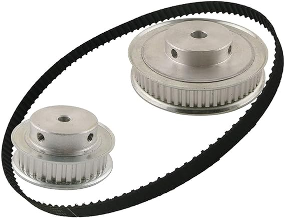
2. Timing Belt:
The timing belt is a toothed belt that runs around the timing pulleys. It has teeth that mesh with the teeth on the timing pulley, creating a positive drive system. The timing belt transmits power from the driving pulley to the driven pulleys while maintaining precise timing and synchronization. Timing belts are typically made of rubber or polymer materials with reinforcing cords for strength.
3. Tensioner:
A tensioner is used to maintain proper tension in the timing belt. It applies tension to the timing belt to prevent slack or excessive tightness, ensuring optimal power transmission and preventing belt skipping or jumping teeth. Tensioners can be spring-loaded or adjustable, depending on the specific system requirements.
4. Idler Pulley:
An idler pulley is an additional pulley used to guide the timing belt and change its direction. It helps to maintain the proper tension and alignment of the timing belt as it wraps around the pulleys. Idler pulleys are typically used in systems with complex routing or when additional support is needed to prevent belt vibration or noise.
5. Shaft or Axle:
The shaft or axle serves as the support for the timing pulleys and allows them to rotate. It is usually connected to a driving source, such as a motor or engine, to provide rotational motion. The shaft or axle needs to be properly aligned and secured to ensure smooth and accurate power transmission.
6. Mounting Hardware:
Mounting hardware includes bolts, screws, or fasteners used to secure the timing pulleys, tensioner, idler pulleys, and other components to their respective locations. The mounting hardware ensures proper alignment and stability of the timing pulley system.
7. Covers and Guards:
In some applications, timing pulley systems may be enclosed with covers or guards for protection. These covers prevent dust, debris, or contaminants from entering the system, which could affect the performance and lifespan of the timing belt and pulleys. Covers and guards also provide a safety barrier, preventing accidental contact with moving parts.
Each of these components plays a crucial role in a timing pulley system, working together to achieve accurate power transmission, precise timing, and synchronization. Proper installation, alignment, and maintenance of these components are essential for the reliable and efficient operation of the timing pulley system.


editor by CX
2024-03-27