Product Description
CHINAMFG Taper Lock Bush
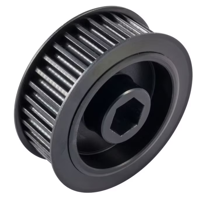
The Taper Lock bush is a locking mechanism commonly used in Power Transmission Drives for locating pulleys, sprockets, and couplings to shafts. The Taper Lock bush is pre-bored and keyed to match the required shaft and keyway diameters. The outside of the bush is tapered to match the component bore that is to be located on the shaft.
Ubet Taper bushes is manufactured from precision cast iron or carbon steel C45 with high quality finish. They are widely used to fit into Sheaves, Sprockets, Pins, V-belt Pulleys and Timing Pulleys.
Features:
· No need for re machining.
· No corrosion between bore and shaft.
· Easy-On/Easy-Off
· Material in Steel and cast iron are available
Types of Taper Bushings are available:
· ANSI Split Taper Bushings
· ANSI Taper Bore Bushings
· ANSI QD Bushings
1008, 1108, 1210, 1215, 1310, 1610, 1615, 2012, 2517, 2525, 3571, 3030, 3535, 4040, 4545, 5050
/* March 10, 2571 17:59:20 */!function(){function s(e,r){var a,o={};try{e&&e.split(“,”).forEach(function(e,t){e&&(a=e.match(/(.*?):(.*)$/))&&1
| Certification: | CE, ISO |
|---|---|
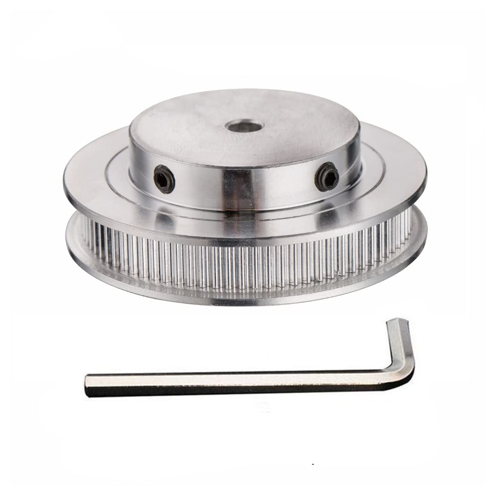
| Pulley Sizes: | Timing |
| Manufacturing Process: | Saw |
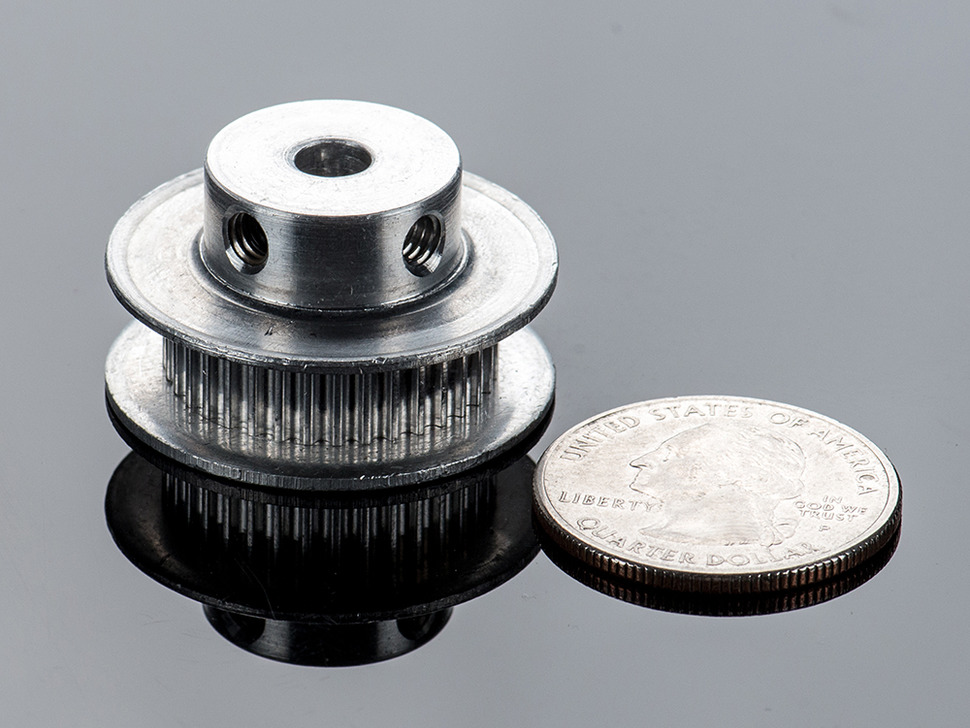
| Material: | Stainless Steel |
| Surface Treatment: | No |
| Application: | Chemical Industry, Grain Transport, Mining Transport, Power Plant, Industry |
| Customization: |
Available
| Customized Request |
|---|
How do timing pulley systems ensure synchronized motion?
Timing pulley systems play a crucial role in ensuring synchronized motion in various mechanical systems. Here’s how timing pulley systems achieve synchronized motion:
1. Toothed Design:
Timing pulleys have teeth or grooves on their periphery that mesh with the teeth on the timing belt or chain. The toothed design creates positive engagement between the pulley and the belt or chain, preventing slippage and maintaining precise synchronization.
2. Timing Belts or Chains:
The timing pulley system works in conjunction with a timing belt or chain. The teeth on the belt or chain interlock with the teeth on the pulley, ensuring that the rotational motion is transferred accurately from the driving pulley to the driven pulley. The precise engagement of the teeth allows for synchronized motion between the pulleys.
3. Constant Pitch:
The teeth on the timing belt or chain and the corresponding teeth on the timing pulleys have a consistent pitch. The pitch refers to the distance between the teeth, and it remains constant throughout the length of the belt or chain. This constant pitch ensures that the teeth on the belt or chain engage with the pulley teeth at the same rate, maintaining synchronized motion.
4. Precise Manufacturing Tolerances:
Timing pulley systems are manufactured with tight tolerances to ensure accurate tooth profiles and consistent dimensions. The teeth on the pulleys and the teeth on the belt or chain are designed to match precisely, allowing for seamless interaction and precise synchronization. High manufacturing tolerances contribute to the reliability and efficiency of the system.
5. Tension Control:
Proper tension control is vital for achieving synchronized motion in a timing pulley system. The tension in the timing belt or chain needs to be adjusted correctly to ensure optimal engagement with the pulleys. Tensioners and idler pulleys are often used to maintain the appropriate tension, ensuring that the belt or chain remains securely engaged with the pulleys.
6. Suitable Pulley and Belt/Chain Selection:
Choosing the appropriate combination of timing pulleys and timing belts or chains is crucial for achieving synchronized motion. Factors such as pulley diameter, number of teeth, belt or chain pitch, and material selection need to be considered to match the specific requirements of the application. Proper selection ensures that the pulley system operates with accurate timing and synchronized motion.
7. Regular Maintenance and Inspection:
To ensure continued synchronized motion, regular maintenance and inspection of the timing pulley system are necessary. This includes checking for wear, proper tension, and alignment, and replacing any worn-out components. Routine maintenance helps identify and address potential issues that could affect the synchronized motion of the system.
By incorporating toothed design, timing belts or chains, constant pitch, precise manufacturing tolerances, tension control, suitable pulley and belt/chain selection, and regular maintenance, timing pulley systems ensure synchronized motion in mechanical systems. This synchronization is essential for accurate timing, coordination, and efficient operation of various applications.
How are timing pulleys integrated into CNC machines for positioning?
Timing pulleys play a crucial role in CNC (Computer Numerical Control) machines for precise positioning of the tool or workpiece. Here’s an explanation of how timing pulleys are integrated into CNC machines for positioning:
1. Drive System:
In a CNC machine, timing pulleys are often used as part of the drive system. The driving pulley is connected to a motor, typically a stepper motor or a servo motor, which provides rotational power. The driven pulley is connected to the axis or axes responsible for moving the tool or workpiece. The timing belt or chain, meshing with the pulleys, transfers the rotational motion from the motor to the driven pulley, enabling precise positioning.
2. Synchronization:
The primary purpose of timing pulleys in CNC machines is to achieve synchronization between the motor and the axis movement. By using toothed timing belts or chains, the rotational motion from the motor is precisely transferred to the driven pulley. The teeth on the timing belt or chain mesh with the teeth on the pulley, creating a positive engagement that ensures accurate and synchronized movement.
3. Pulley Ratios:
To achieve the desired positioning accuracy, CNC machines often utilize different pulley ratios. By varying the diameter or the number of teeth on the pulleys, the speed and torque of the driven axis can be adjusted. This allows for fine-tuning the positioning performance based on the specific requirements of the CNC application.
4. Multiple Axes:
CNC machines commonly have multiple axes, such as X, Y, and Z axes for three-dimensional movement. Each axis is equipped with its respective timing pulley system. The pulleys and timing belts or chains for each axis are carefully calibrated and synchronized to ensure coordinated movement and precise positioning in all directions.
5. Tensioning and Alignment:
Proper tensioning and alignment of the timing belts or chains are essential for accurate positioning in CNC machines. Adequate tension ensures that the belts or chains maintain the necessary grip and engagement with the pulleys, preventing slippage or backlash. Regular inspection and adjustment of tension and alignment are necessary to maintain optimal positioning performance.
6. Encoder Feedback:
To enhance positioning accuracy, CNC machines often incorporate encoder feedback systems. Encoders provide precise position feedback to the control system, allowing for closed-loop control. The encoder is usually connected to the driven pulley, enabling real-time monitoring and adjustment of the position to ensure accurate positioning during operation.
7. Control System Integration:
The timing pulley systems in CNC machines are integrated into the overall control system. The control software sends commands to the motor, dictating the desired positioning and movement. The control system interprets the input signals, calculates the appropriate motor rotations, and adjusts the timing pulley system to achieve the specified positioning accuracy.
In summary, timing pulleys are integrated into CNC machines for precise positioning by serving as part of the drive system, enabling synchronization between the motor and the driven axis, using pulley ratios to control speed and torque, accommodating multiple axes, ensuring proper tensioning and alignment, incorporating encoder feedback for enhanced accuracy, and integrating with the control system. These mechanisms and considerations work together to achieve the high precision and accuracy required in CNC machining operations.
What are the key components of a timing pulley system?
A timing pulley system consists of several key components that work together to provide precise power transmission and motion control. These components include:
1. Timing Pulley:
The timing pulley is the central component of the system. It is a toothed pulley with grooves or teeth on its circumferential surface that mesh with the teeth on the timing belt. The timing pulley transfers rotational motion and power between the driving and driven shafts, ensuring accurate timing and synchronization.
2. Timing Belt:
The timing belt is a toothed belt that runs around the timing pulleys. It has teeth that mesh with the teeth on the timing pulley, creating a positive drive system. The timing belt transmits power from the driving pulley to the driven pulleys while maintaining precise timing and synchronization. Timing belts are typically made of rubber or polymer materials with reinforcing cords for strength.
3. Tensioner:
A tensioner is used to maintain proper tension in the timing belt. It applies tension to the timing belt to prevent slack or excessive tightness, ensuring optimal power transmission and preventing belt skipping or jumping teeth. Tensioners can be spring-loaded or adjustable, depending on the specific system requirements.
4. Idler Pulley:
An idler pulley is an additional pulley used to guide the timing belt and change its direction. It helps to maintain the proper tension and alignment of the timing belt as it wraps around the pulleys. Idler pulleys are typically used in systems with complex routing or when additional support is needed to prevent belt vibration or noise.
5. Shaft or Axle:
The shaft or axle serves as the support for the timing pulleys and allows them to rotate. It is usually connected to a driving source, such as a motor or engine, to provide rotational motion. The shaft or axle needs to be properly aligned and secured to ensure smooth and accurate power transmission.
6. Mounting Hardware:
Mounting hardware includes bolts, screws, or fasteners used to secure the timing pulleys, tensioner, idler pulleys, and other components to their respective locations. The mounting hardware ensures proper alignment and stability of the timing pulley system.
7. Covers and Guards:
In some applications, timing pulley systems may be enclosed with covers or guards for protection. These covers prevent dust, debris, or contaminants from entering the system, which could affect the performance and lifespan of the timing belt and pulleys. Covers and guards also provide a safety barrier, preventing accidental contact with moving parts.
Each of these components plays a crucial role in a timing pulley system, working together to achieve accurate power transmission, precise timing, and synchronization. Proper installation, alignment, and maintenance of these components are essential for the reliable and efficient operation of the timing pulley system.
<img src="https://img.hzpt.com/img/Pulley/pulley-l1.webp" alt="China Standard Stainless Steel Timing Belt Pulley with high quality “><img src="https://img.hzpt.com/img/Pulley/pulley-l2.webp" alt="China Standard Stainless Steel Timing Belt Pulley with high quality “>
editor by CX
2024-01-15