
EP-XL 5.08MM Aluminum Straight Bore Timing Pulley
The EP-XL 5.08mm Aluminum Straight Bore Timing Pulley are precision-engineered for synchronous drive systems requiring a 5.08mm pitch. Available in tooth counts ranging from 10 to 72, these pulleys offer versatile speed ratio options for diverse industrial applications. Constructed from high-quality aluminum or steel, they ensure durability and lightweight performance.
Key dimensions include a consistent flange width (F) of 14.3mm. Models with 10-22 teeth feature a 20-22mm length (L), while larger models (26-72 teeth) extend to 25mm. The series accommodates various bore sizes (Dm), starting from 9.5mm for smaller pulleys up to 100mm for the largest 68-72 tooth variants. With precise outer diameters (De) spanning from 15.66mm to 115.92mm, these pulleys provide accurate transmission for automation, robotics, and machinery.
EP-XL 5.08MM Aluminum Straight Bore Timing Pulley
Precision Machined XL Pitch Straight Bore Timing Belt Pulley — Aluminum and Steel, 10 to 72 Teeth, Global Supply
1. XL 037 (5.08 mm) — Full Dimensional Specification Table
All dimensions in millimeters. Dp = Pitch Diameter; De = Outside Diameter; Df = Flange Diameter; Dm = Body Diameter; Di = Inner Diameter; F = Face Width; L = Hub Length; d = Bore Reference. Material: AL (Aluminum) or STEEL. Dash (—) indicates dimension not applicable for that type.
| Part Code | Teeth | Type | Material | Dp | De | Df | Dm | F | L | d | Flange No. |
|---|---|---|---|---|---|---|---|---|---|---|---|
| 10 XL 037 | 10 | 6F | AL/STEEL | 16.17 | 15.66 | 23 | 9.5 | 14.3 | 20 | — | 1 |
| 11 XL 037 | 11 | 6F | AL/STEEL | 17.79 | 17.28 | 23 | 9.5 | 14.3 | 20 | — | 1 |
| 12 XL 037 | 12 | 6F | AL/STEEL | 19.40 | 18.90 | 25 | 10 | 14.3 | 20 | — | 2 |
| 13 XL 037 | 13 | 6F | AL/STEEL | 21.02 | 20.51 | 25 | 10 | 14.3 | 20 | — | 2 |
| 14 XL 037 | 14 | 6F | AL/STEEL | 22.64 | 22.13 | 28 | 15 | 14.3 | 20 | — | 4 |
| 15 XL 037 | 15 | 6F | AL/STEEL | 24.26 | 23.75 | 28 | 15 | 14.3 | 20 | — | 4 |
| 16 XL 037 | 16 | 6F | AL/STEEL | 25.87 | 25.36 | 32 | 16 | 14.3 | 20 | — | 5 |
| 17 XL 037 | 17 | 6F | AL/STEEL | 27.49 | 26.98 | 32 | 20 | 14.3 | 20 | — | 6 |
| 18 XL 037 | 18 | 6F | AL/STEEL | 29.11 | 28.60 | 35 | 20 | 14.3 | 20 | — | 7 |
| 19 XL 037 | 19 | 6F | AL/STEEL | 30.72 | 30.22 | 35 | 20 | 14.3 | 22 | — | 7 |
| 20 XL 037 | 20 | 6F | AL/STEEL | 32.34 | 31.83 | 38 | 24 | 14.3 | 22 | — | 9 |
| 21 XL 037 | 21 | 6F | AL/STEEL | 33.96 | 33.45 | 38 | 24 | 14.3 | 22 | — | 9 |
| 22 XL 037 | 22 | 6F | AL/STEEL | 35.57 | 35.07 | 41 | 25 | 14.3 | 22 | — | 10 |
| 24 XL 037 | 24 | 6F | AL/STEEL | 38.81 | 38.30 | 44 | 30 | 14.3 | 22 | — | 12 |
| 26 XL 037 | 26 | 6F | AL/STEEL | 42.04 | 41.53 | 48 | 30 | 14.3 | 22 | 8 | 11 |
| 27 XL 037 | 27 | 6F | AL/STEEL | 43.66 | 43.15 | 48 | 34 | 14.3 | 22 | 8 | 11 |
| 28 XL 037 | 28 | 6F | AL/STEEL | 45.28 | 44.77 | 51 | 34 | 14.3 | 22 | 8 | 16 |
| 30 XL 037 | 30 | 6F | AL/STEEL | 48.51 | 48.00 | 54 | 38 | 14.3 | 22 | 8 | 18 |
| 32 XL 037 | 32 | 6F | AL/STEEL | 51.74 | 51.24 | 57 | 38 | 14.3 | 25 | 8 | 20 |
| 34 XL 037 | 34 | 6 | AL/STEEL | 54.98 | 54.47 | — | 45 | 14.3 | 25 | 8 | — |
| 36 XL 037 | 36 | 6 | AL/STEEL | 58.21 | 57.70 | — | 45 | 14.3 | 25 | 8 | — |
| 40 XL 037 | 40 | 6 | AL/STEEL | 64.68 | 64.17 | — | 45 | 14.3 | 25 | 8 | — |
| 44 XL 037 | 44 | 6 | AL/STEEL | 71.15 | 70.64 | — | 45 | 14.3 | 25 | 8 | — |
| 45 XL 037 | 45 | 6W | AL/STEEL | 72.77 | 72.26 | — | 45 | 14.3 | 25 | 10 | — |
| 48 XL 037 | 48 | 6W | AL/STEEL | 77.62 | 77.11 | — | 45 | 14.3 | 25 | 10 | — |
| 52 XL 037 | 52 | 6W | AL/STEEL | 84.08 | 83.58 | — | 45 | 14.3 | 25 | 10 | — |
| 56 XL 037 | 56 | 6W | AL/STEEL | 90.55 | 90.04 | — | 45 | 14.3 | 25 | 10 | — |
| 60 XL 037 | 60 | 6W | AL/STEEL | 97.02 | 96.51 | — | 45 | 14.3 | 25 | 10 | — |
| 68 XL 037 | 68 | 6W | AL/STEEL | 109.96 | 109.45 | — | 45 | 14.3 | 25 | 10 | — |
| 72 XL 037 | 72 | 6W | AL/STEEL | 116.42 | 115.92 | — | 45 | 14.3 | 25 | 10 | — |
Note: Full 46-part range including all intermediate tooth counts (29, 38, 39, 41, 42, 43, 46, 47, 49, 57, 58, 59, 69, 70, 71) is available — contact us for the complete specification sheet. Bore diameter (d) to be specified at order; standard sizes from 6 mm to 25 mm depending on tooth count.
2. About Our XL Series Straight Bore Timing Pulley
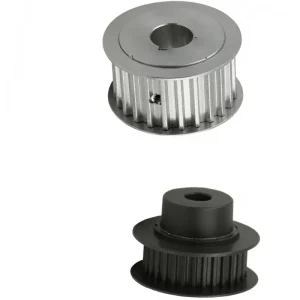
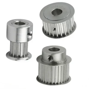
The EP-XL series is a precision-machined straight bore timing pulley manufactured to the XL pitch standard — a 5.08 mm (0.200 inch) tooth pitch that is one of the most widely used belt drive pitch specifications in industrial automation, CNC machinery, robotics, and precision instrumentation worldwide. Unlike taper-lock or QD-bushing pulley designs, the straight bore timing pulley accepts the drive shaft directly through the bore without an intermediate bushing, producing the most compact and dimensionally straightforward shaft-to-pulley assembly available in the timing pulley product family. The bore of each straight bore timing pulley is machined to a finished dimension at manufacture, and a keyway is typically provided for positive torque transmission through a standard parallel key.
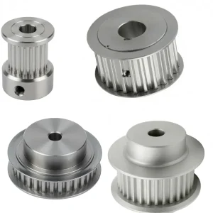
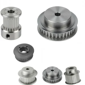
Available in both aluminum (AL) and steel (STEEL) materials across the tooth count range from 10 teeth through 72 teeth, the XL 037 series covers pitch diameters from 16.17 mm (10 teeth) up to 116.42 mm (72 teeth). Three structural types are offered — Type 6F (flanged, for tooth counts 10 through 32), Type 6 (plain, for tooth counts 34 through 44), and Type 6W (wide flanged for tooth counts 45 through 72) — reflecting the standard relationship between tooth count, pulley body width requirement, and the belt-retention flange configuration that prevents lateral belt tracking errors in service. The F dimension (face width of 14.3 mm across the full range) is uniform, simplifying belt selection across different tooth count configurations within the same XL pitch drive system. Understanding the correct timing belt pulley type for each application — flanged, plain, or wide-web — is essential when specifying a straight bore timing pulley for a new or replacement drive.
The XL series aluminum timing pulley variant is the standard choice for the majority of light-to-medium industrial drive applications where weight minimization, corrosion resistance, and ease of machining post-purchase are valued over the higher torque capacity of the steel alternative. The aluminum construction of this straight bore timing pulley significantly reduces rotational inertia compared to a steel pulley of the same tooth count — a practically important characteristic in servo-driven systems where the total reflected inertia determines servo motor sizing and dynamic response bandwidth. The steel variant is specified where higher torque density, exposure to abrasive environments, or resistance to shaft key fretting damage at the bore-shaft interface is required.
3. Five Key Product Advantages
The XL tooth profile is an involute-derived trapezoidal form standardized across ANSI/RMA IP-24 and ISO 5294, ensuring that an XL pitch belt meshes correctly with any XL pitch pulley regardless of manufacturer origin. This dimensional interchangeability is critical for maintenance-driven procurement: replacement XL pulleys must mesh precisely with the existing belt to preserve the synchronous (zero-slip) nature of the drive. The straight bore timing pulley tooth profile is cut to the XL standard tooth geometry — tooth height, tooth root radius, and tooth flank angle — on CNC hobbing or forming machines, and verified dimensionally before dispatch. This precision tooth form eliminates the belt-tooth clearance variation that causes timing error in position-critical servo and stepper motor drive systems where a straight bore timing pulley is the preferred interface between motor shaft and belt.
The aluminum timing pulley variant of the XL straight bore timing pulley uses 6061-T6 or equivalent structural aluminum alloy, providing tensile strength in the 260–310 MPa range that is adequate for the belt tension loads in standard XL pitch drive systems. The aluminum's density of approximately 2.7 g/cm³ — roughly one-third of steel — produces a straight bore timing pulley that is substantially lighter for any given tooth count and diameter. At 40 teeth with a pitch diameter of 64.68 mm, the aluminum straight bore timing pulley weighs approximately one-third of its steel equivalent, reducing shaft bearing loads and motor inertia contribution. The natural oxide layer that forms on aluminum surfaces provides adequate corrosion protection for indoor industrial environments; for outdoor or chemical exposure applications, the steel variant or an anodized aluminum straight bore timing pulley option is recommended.
The XL 037 straight bore timing pulley series covers 46 distinct part numbers from 10 XL 037 (10 teeth, Dp 16.17 mm) through 72 XL 037 (72 teeth, Dp 116.42 mm), providing a continuous range of drive ratios from a single catalogued product family. This comprehensive range means that a drive designer can achieve any required speed ratio from approximately 1:7.2 (10-tooth driver, 72-tooth driven) to 7.2:1 within a single pitch and face width standard, without combining pulleys from different series or pitch families. The wide range also accommodates center distance optimization: selecting tooth counts that produce the required ratio while keeping the belt wrap angle at both straight bore timing pulley positions above the 90-degree minimum recommended for synchronous belt drive reliability.
The three type designations in the XL 037 series — 6F (double flange, small tooth counts), 6 (plain, mid-range), and 6W (wide web, large tooth counts) — provide the correct belt retention geometry across the tooth count range for each straight bore timing pulley configuration. Flanged straight bore timing pulley units (Type 6F) provide physical lateral containment for the belt, preventing the belt from tracking off the pulley under misalignment or side-load conditions — critical for small tooth-count (small diameter) pulleys where the belt's tendency to track off is highest. The plain Type 6 and wide Type 6W configurations for larger diameters rely on the belt's natural lateral stiffness and the drive geometry for tracking, eliminating flange-induced belt edge wear that can occur on large-diameter flanged straight bore timing pulley units. This engineered progression through structural types across the tooth count range reflects the timing belt pulley design standards compiled from decades of industrial drive experience.
The straight bore timing pulley is bored to a finished standard diameter with a parallel keyway — the most mechanically straightforward shaft-to-pulley connection in industrial drive systems. The bore diameter of each straight bore timing pulley is typically specified to an H7 tolerance, accepting a standard keyed shaft in a close running or light press fit depending on the drive torque and reversing load requirements. For the majority of XL pitch drive applications — light to medium conveyor drives, CNC axis drives, and indexing mechanisms — the keyway provides adequate torque transmission capacity without the additional mechanical complexity of taper-lock or keyless shrink disc retention systems. The bored-and-keyed connection of this straight bore timing pulley also allows the pulley to be repositioned axially on the shaft for belt alignment adjustment, a practical advantage in field installation and maintenance.
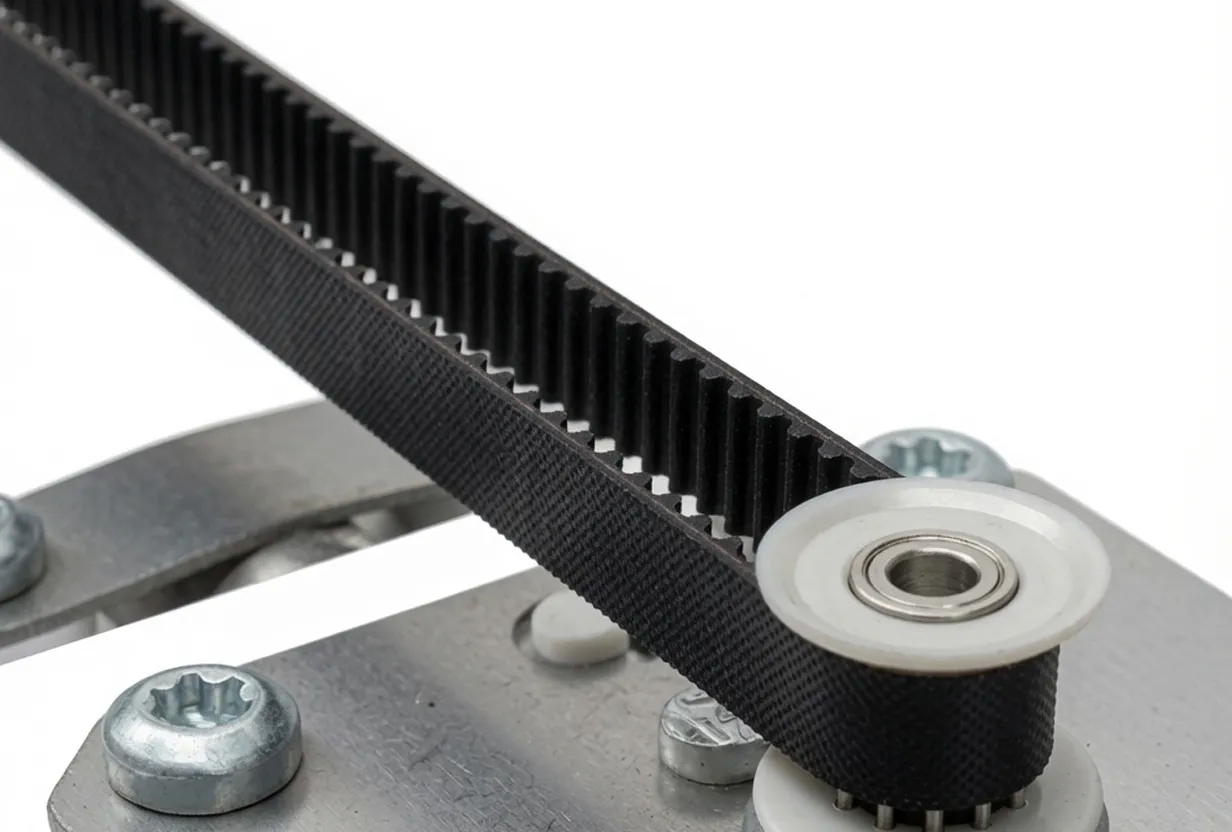
4. How the XL Timing Belt and Straight Bore Timing Pulley Drive Works
The timing belt pulley and belt system transmits rotary motion between shafts through positive mechanical engagement between the belt teeth and the pulley tooth spaces, rather than through friction as V-belt or flat belt systems do. The XL pitch specifies the exact dimensional relationship between belt teeth and straight bore timing pulley tooth spaces: the 5.08 mm pitch (center-to-center distance between adjacent belt teeth) must equal the pitch circle spacing of the straight bore timing pulley teeth, which is the pitch diameter divided by the tooth count times pi. At any instant, multiple teeth are simultaneously in engagement — the number in engagement depends on the belt wrap angle around the straight bore timing pulley and the tooth pitch — distributing the transmitted load across these teeth and providing the redundancy that makes synchronous belt drives more reliable than single-tooth engagement mechanisms.
The term "synchronous" in timing belts and pulleys refers to the fact that the angular velocity ratio between input and output shafts is exactly determined by the straight bore timing pulley tooth count ratio, with no slip. A 20-tooth driving straight bore timing pulley turning at 1500 rpm drives a 40-tooth driven straight bore timing pulley at exactly 750 rpm regardless of load, within the elastic deformation limits of the belt under tension. This synchronous behavior is what distinguishes timing belt drives from V-belt drives (which slip under overload and exhibit speed variation under load fluctuation) and makes them indispensable in applications where shaft position accuracy or constant velocity ratio matters — CNC machine tool axes, printing press registration drives, indexing conveyors, and robotic joint drives.
The XL straight bore timing pulley is the smaller-pitch alternative to XH, H, and L pitch pulleys, producing a finer tooth pitch that suits lower power, higher-speed, precision drives. At 5.08 mm pitch, the XL series handles drive powers from approximately 0.1 kW at high speeds through approximately 2–3 kW at lower speeds for standard belt widths, making it appropriate for servo axis drives, stepper motor-driven positioning systems, small conveyor indexing drives, and precision instrument mechanisms. The straight bore timing pulley in the XL series is the direct interface between the motor or drive shaft and the belt, and its dimensional accuracy — tooth profile, pitch accuracy, bore concentricity, and face runout — directly determines the transmission accuracy, belt life, and noise level of the complete timing belt drive pulley system.
5. Straight Bore Timing Pulley Selection and Procurement Guide
Selecting the correct straight bore timing pulley for an XL pitch drive requires confirming four parameters before ordering: tooth count, material, bore diameter, and structural type (6F, 6, or 6W). The tooth count determines the pitch diameter and therefore the drive ratio — the ratio of driven to driving straight bore timing pulley tooth counts equals the inverse of the speed ratio. For example, a drive requiring a 2:1 speed reduction pairs a 20-tooth driving straight bore timing pulley with a 40-tooth driven straight bore timing pulley. The pitch diameter difference between these two pulleys determines the minimum center distance for adequate belt wrap angle.
Material selection between the aluminum timing pulley and steel options for a given straight bore timing pulley depends on the drive's torque level, cycling duty, and environmental exposure. The aluminum straight bore timing pulley is suitable for the majority of servo and stepper motor positioning drives up to the rated torque of standard XL belts; the steel straight bore timing pulley becomes the correct choice when bore fretting damage at the keyway interface is observed under heavy reversing load or when the environment includes abrasive particles that would accelerate surface wear on the softer aluminum. Many designs use a steel straight bore timing pulley on the motor shaft (where keyway reversing loads are highest) and an aluminum straight bore timing pulley on the driven shaft (where lower inertia is the priority).
Bore diameter specification is the most frequently mishandled parameter in straight bore timing pulley procurement. The bore must exactly match the shaft diameter — an oversized bore allows lateral runout that causes belt-tracking errors, while an undersized bore requires force fitting that can crack the straight bore timing pulley hub. Always specify the bore diameter to H7 tolerance unless the application specifically requires a tighter fit. For intermediate bore sizes not listed in the standard range, our engineering team can machine custom bore diameters in any straight bore timing pulley size within the XL 037 series at production lead times that suit most standard procurement timelines.
6. Materials: Aluminum and Steel Straight Bore Timing Pulley Options
The XL 037 straight bore timing pulley is available in two material variants that cover the complete range of performance requirements encountered in the XL pitch drive application spectrum. The aluminum variant uses 6061-T6 aluminum alloy as the standard specification — a heat-treatable structural alloy containing silicon, magnesium, and trace manganese that achieves 0.2% proof strength of approximately 275 MPa and ultimate tensile strength of approximately 310 MPa in the T6 temper condition. This strength level is adequate for XL pitch belt drives operating at standard belt tensions, and the alloy's excellent machinability allows tight dimensional tolerances to be held during CNC turning and milling of the tooth form and bore without the tool wear and dimensional drift that harder materials produce. The aluminium timing pulley surface can be left as-machined, chemically treated (chromate conversion), or hard anodized for additional surface hardness and corrosion resistance in applications where bare aluminum would be insufficient for this type of straight bore timing pulley.
The steel variant of this straight bore timing pulley uses medium-carbon or medium-carbon alloy steel (typically 45C or 40Cr equivalent) that provides approximately 2–3 times the tensile strength of the aluminum alternative and significantly higher surface hardness at the bore-keyway interface, where fretting wear from cyclic torque transmission can cause progressive hub enlargement over time in aluminum pulleys under heavy cycling. Steel is the correct choice for timing belt pulley applications involving high torque-to-diameter ratios, significant reversing loads, or vibration that would cause fretting at the shaft-bore interface of the straight bore timing pulley. The steel surface requires corrosion protection — either black oxide treatment for indoor service or zinc plating for more aggressive environments — since steel's corrosion resistance is substantially lower than aluminum's in the presence of moisture.
The face width F = 14.3 mm is consistent across the entire tooth count range in the XL 037 straight bore timing pulley series, which means that the same XL standard belt (6.4 mm nominal width for XL 037 designation) tracks correctly across all tooth counts without requiring different belt widths for different straight bore timing pulley sizes in the same drive system. This dimensional uniformity is a significant procurement advantage for machine builders who use multiple XL pitch pulley tooth counts in the same machine: a single belt width sourcing relationship covers all straight bore timing pulley positions in the design.
7. Application Scenarios
The XL pitch straight bore timing pulley serves precision motion and synchronous drive requirements across a broad range of industries globally. The 5.08 mm pitch provides the ideal balance between belt tooth strength and drive compactness for light-to-medium power applications where timing accuracy and belt life are the primary design criteria.
CNC milling machines, lathes, laser cutters, and plasma cutting systems use timing belt pulley and belt drives to transfer motor torque from the servo or stepper motor to the lead screw or rack-and-pinion drive axis. The XL pitch provides sufficient tooth engagement strength for the belt tensions generated in these applications, and the synchronous nature of the drive ensures that the controller's commanded motor position accurately corresponds to the axis physical position — a fundamental requirement for CNC positioning accuracy. The straight bore timing pulley is the standard interface in these drives precisely because its compact, bushingless design suits the tight packaging of servo axis drive packages. The timing belt idler pulley is often incorporated in these circuits to maintain belt tension as the axis approaches the center distance change caused by thermal expansion of the machine structure.
Industrial robot joints, collaborative robot (cobot) arm links, and SCARA robot axes use lightweight aluminum timing pulley belt stages to achieve speed reduction between the servo motor and the structural joint without the backlash and weight penalty of gear trains. The XL series straight bore timing pulley is widely used in belt-reduction stages within robot arm links where envelope constraints require compact, flat drive packages, and where the low weight of the straight bore timing pulley contributes to minimizing the arm's self-weight — a primary design objective in collaborative robots that must carry themselves plus the rated payload within the joint torque budget.
Sheet-fed and web-fed printing machines, packaging line conveyors, and labeling systems require constant velocity ratio drives with zero slip to maintain print registration accuracy and product placement precision as line speeds increase. The synchronous timing belt drive pulley is the standard solution for these applications, and the XL pitch straight bore timing pulley is appropriate for the moderate power and high-speed operating conditions of medium-format printing and packaging equipment. The timing pulley standard sizes of the XL 037 series align with the belt and straight bore timing pulley specifications that major European and North American printing machinery OEMs have standardized into their machine platforms over decades of production.
Medical imaging equipment (CT scanners, MRI positioning tables, X-ray positioning systems), laboratory automation (liquid handling robots, microplate movers, centrifuge control mechanisms), and diagnostic instrument drives use XL pitch straight bore timing pulley units in precision motion stages where repeatability and low noise are equally important. The aluminum straight bore timing pulley in this application offers the additional advantage of being MRI-compatible in environments where ferromagnetic materials produce hazardous projectile risks. Custom bore sizes to fit the small diameter motor shafts common in medical drive systems are available, and the straight bore timing pulley profile meets the dimensional precision requirements for medical equipment motion control standards including IEC 60601 applicable drive components.
Desktop and industrial 3D printers — FDM, SLA, SLS, and material jetting types — use XL pitch or smaller pitch timing belt pulley systems for their print head positioning axes (typically X and Y), with the aluminum straight bore timing pulley contributing to the low moving mass that is essential for high acceleration at the print head without exceeding the stepper motor's torque budget. The XL pitch 5.08 mm tooth spacing is the most common tooth pitch in the desktop 3D printer and professional additive manufacturing equipment market, and the timing belt pulley replacement market for these machines is substantial globally, driven by wear, accidental damage, and performance upgrade activities across the large installed base of both hobbyist and professional additive manufacturing systems.
8. Standards Compliance and Regulatory Framework
The XL pitch straight bore timing pulley and the timing belt systems in which it operates are governed by dimensional standards that ensure interchangeability and performance predictability across different manufacturers and geographic markets. Understanding the applicable standards framework helps engineers and procurement teams verify dimensional compliance and select compatible products across different supply sources.
The American National Standard ANSI/RMA IP-24 defines the tooth form, pitch, and dimensional tolerances for synchronous belt drives in the MXL, XL, L, H, XH, and XXH pitch families. The XL pitch (5.08 mm) is fully specified in this standard, including straight bore timing pulley tooth form dimensions, pitch circle diameter calculation formulas, and belt width designations. This standard is the reference for China timing pulley manufacturers who supply global markets and need to verify compatibility with belts sourced to ANSI standards. The standard is maintained by the Rubber Manufacturers Association and is the primary reference for North American market synchronous drive design using the straight bore timing pulley and related components.
ISO 5294 (Synchronous Belt Drives — Pulleys) and ISO 5296 (Synchronous Belt Drives — Belts: Dimensional Requirements) provide the international equivalent of the ANSI standards for synchronous belt drive components. These standards cover the same pitch families including XL pitch and specify the dimensional requirements that a straight bore timing pulley must meet for interchangeability across ISO-compliant products. European, Japanese, Korean, and Australian market machine builders reference ISO 5294 in their component specifications, and timing pulley manufacturers supplying these markets must demonstrate compliance with ISO 5294 dimensional requirements for the straight bore timing pulley.
Drive components including timing belt pulley sets installed in machinery sold in the European Union must be designed and selected to meet the essential health and safety requirements of the Machinery Directive. Timing belt drives incorporating a straight bore timing pulley in safety-relevant positions — such as robotic joint drives, medical positioning systems, and automated machinery — must be specified with adequate design safety factors and the belt life calculations must account for the machinery's designed service life. Buyers incorporating XL straight bore timing pulley units into CE-marked machinery should obtain dimensional compliance documentation and material certificates as part of the technical file.
The Japanese Industrial Standard JIS B 1856 governs synchronous belt drive pulleys for the Japanese market. The XL pitch dimensions in JIS B 1856 are dimensionally equivalent to ANSI/RMA IP-24 and ISO 5294 for the XL series, allowing Japanese-standard machines to use XL straight bore timing pulley units sourced internationally without dimensional conflict. Japanese automation and machine tool manufacturers — among the world's most demanding users of metric timing pulleys and synchronous drive components — specify straight bore timing pulley dimensional accuracy to JIS tolerances that are equivalent to or more stringent than ISO 5294.
9. Compatible Products for Complete Drive Systems
A complete synchronous timing belt drive system requires matched timing belt pulley components including the straight bore timing pulley, and often includes complementary products for tension adjustment, shaft-to-pulley connection, and system speed ratio optimization. We supply matched products across the complete timing drive component range.
Metric Pitch Standard Toothed Bars provide the linear rack equivalent of the rotary straight bore timing pulley for linear positioning applications. When a timing belt wraps around a straight bore timing pulley and meshes with a toothed rack, the rotational motion of the straight bore timing pulley produces precise linear translation of the belt and carriage system — the operating principle used in many CNC gantry systems, 3D printer bed drives, and linear conveyor indexing mechanisms. Our toothed bar range covers the same pitch standards as the XL straight bore timing pulley series, ensuring dimensional compatibility for system designs that combine rotary pulley and linear rack components within the same drive architecture.
In multi-stage drive systems where timing belt synchronization handles the precision positioning requirement and a V-belt pulley drive handles the primary power transmission from a higher-power motor to the timing belt stage input, both pulley types must be selected for mechanical compatibility at the shared shaft. Our V-belt pulley range covers all standard groove profiles — SPA, SPB, SPC, A, B, C, D sections — in cast iron, steel, and aluminum, providing the primary power stage counterpart to the XL straight bore timing pulley precision stage in multi-stage machine drives where cost and efficiency balance determines the split between V-belt and synchronous belt stages using the straight bore timing pulley.

10. About Us
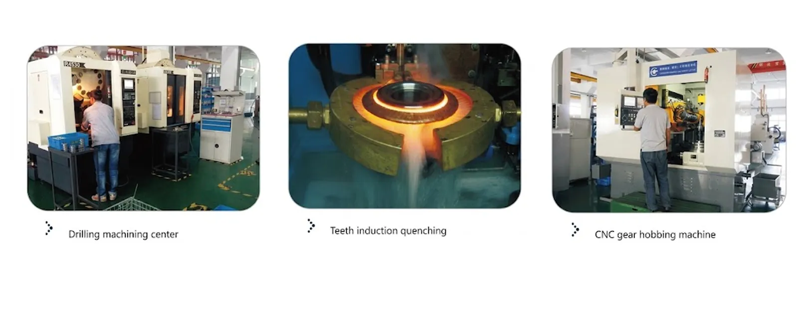
We are a specialized timing pulley manufacturer with production capability across the complete range of synchronous belt drive pulleys — including the XL straight bore timing pulley, L, H, XH, XXH, MXL, T2.5, T5, T10, AT5, AT10, HTD 3M, HTD 5M, HTD 8M, and custom pitch configurations. Our production facility is equipped with CNC turning centers, CNC milling machines, CNC gear hobbing equipment, and precision measurement systems that verify tooth profile accuracy, pitch circle runout, and bore concentricity to the dimensional tolerances specified in ANSI/RMA IP-24 and ISO 5294 for each straight bore timing pulley unit. We manufacture both catalogued timing pulley stock items for immediate shipment and custom straight bore timing pulley units to buyer-specified bore diameters, hub lengths, materials, and surface treatments.
WorkShop


Frequently Asked Questions
Editor: PXY