Produktbeskrivning
OEM ODM Customized High Torque Timing Pulley With Stainless Steel
Synchronous belt pulley transmission is composed of an annular belt with equidistant teeth on the inner peripheral surface and a belt pulley with corresponding teeth. During operation, the belt teeth mesh with the tooth slots of the belt pulley to transmit motion and power. It is a new belt transmission that integrates the respective advantages of belt transmission, chain transmission and gear transmission.
Product Parameters
| Product | standard timing belt pulley & idler pulley |
| Customized | OEM, drawings or samples customized |
| Teeth type | Normal Torque Drive Type:MXL,XL,L,H,XH,XXH High Torque Drive Type:S2M,S3M,S5M,S8M,HTD2M,HTD3M,HTD5M,HTD8M,P2M,P3M,P5M,P8M High Precision Position Drive Type:2GT,3GT,5GT,8YU Light Load Drive Type:T5,T10,T20 Heavy Load Drive Type:AT5,AT10,AT20 |
| Basic shape | Type A,Type B,Type D,Type E,Type F,Type K |
| Adaption | Adapt to 1/4 inch,5/16 inch,1/2 inch, 3/8inch, 2/25inch, 1/5inch belt |
| surface treatment | Natural color anodizing,Black anodizing,Hard anodizing,Ni-plating,Blackening |
| Material | 6061(aluminum),S45C(45# steel),SUS304(Stainless steel) |
| Bore | Pilot bore, Taper bore and Customized bore. |
| Tolerance Control | Outer diameter ±0.005mm Length dimension ±0.05mm |
| Standard | DIN, ISO/GB, AGMA, JIS |
| Teeth Accuracy | DIN Class 4, ISO/GB Classs 4, AGMA Class 13, JIS Class 0 |
| Weight | Max 15Tons |
| testing equipment | projecting apparatus,salt spray test,durometer,and coating thickness tester,2D projector |
| producing equipment | CNC machine,automatic lathe machine,stamping machine,CNC milling machine,rolling machine,lasering,tag grinding machine etc. |
| Machining Process | Gear Hobbing, Gear Milling, Gear Shaping, Gear Broaching,Gear Shaving, Gear Grinding and Gear Lapping |
| Application industry | Robot industry,Medical industry,Making machine industry,Automation industry,3C industry equipment,Packaging industry,UAV industry,New energy industry. |
Företagsprofil
Förpackning och frakt
| lead time | 10-15 working days as usual,30days in busy season,it will based on the detailed order quantity |
| Delivery of samples | by DHL,Fedex,UPS,TNT,EMS |
FAQ
| Main markets | Southeast Asia, North America, Eastern Europe, Mid-East, West Europe |
| How to order | *You send us drawing or sample |
| *We carry through project assessment | |
| *We give you our design for your confirmation | |
| *We make the sample and send it to you after you confirmed our design | |
| *You confirm the sample then place an order and pay us 30% deposit | |
| *We start producing | |
| *When the goods is done,you pay us the balance after you confirmed pictures or tracking numbers | |
| *Trade is done,thank you! |
/* 22 januari 2571 19:08:37 */!function(){function s(e,r){var a,o={};try{e&&e.split(“,”).forEach(function(e,t){e&&(a=e.match(/(.*?):(.*)$/)))
| Certification: | CE, ISO |
|---|---|
| Pulley Sizes: | Type B |
| Tillverkningsprocess: | Forging |
| Material: | Aluminum |
| Ytbehandling: | Electroplating |
| Ansökan: | Chemical Industry, Grain Transport, Mining Transport, Power Plant, Printing Machinery |
| Prover: | US$ 10/Piece 1 styck (minsta beställning) | |
|---|
| Anpassning: | Tillgänglig | Anpassad förfrågan |
|---|
Hur bidrar kamremskivor till effektiv kraftfördelning?
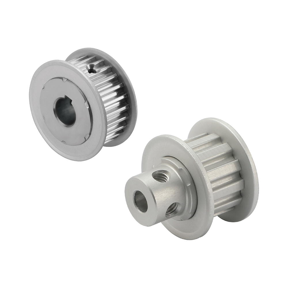
Kamremskivor spelar en avgörande roll för att säkerställa effektiv kraftfördelning i olika mekaniska system. Så här bidrar kamremskivor till effektiv kraftfördelning:
1. Exakt timing och synkronisering:
Kamremskivor, i kombination med kamremmar eller kedjor, synkroniserar rotationen av olika komponenter i ett system. Genom att upprätthålla exakt timing mellan ingångs- och utgående axlar säkerställer kamremskivor att kraften fördelas korrekt och effektivt. Denna synkronisering förhindrar effektförlust på grund av feljustering eller tidsavvikelser.
2. Positivt drivsystem:
Kamremskivor skapar ett positivt drivsystem när de kombineras med kamremmar eller kedjor. Tänderna på remskivorna griper tag ihop med tänderna på remmen eller kedjan, vilket skapar ett fast grepp som eliminerar slirning. Denna positiva drivning säkerställer att kraften överförs effektivt från drivremskivan till den drivna remskivan utan energiförlust.
3. Lastfördelning:
Kamremskivor hjälper till att fördela lasten jämnt över systemet genom att överföra kraft från drivremskivan till den drivna remskivan. Remskivans design och kuggprofil gör att lasten kan fördelas över en större kontaktyta, vilket minskar spänningskoncentrationen på enskilda komponenter. Denna jämna lastfördelning förbättrar kraftöverföringens totala effektivitet.
4. Minskad friktion och slitage:
Kamremskivor, särskilt de som är tillverkade av material med låga friktionskoefficienter, minimerar friktion och slitage vid kraftöverföring. Det smidiga ingreppet mellan remskivans tänder och remmen eller kedjan minskar energiförluster orsakade av friktion. Dessutom förlänger material med utmärkta slitstyrka remskivornas livslängd, vilket säkerställer långsiktig effektivitet.
5. Spänningskontroll:
Kamremskivor, i kombination med spänn- och mellanremskivor, hjälper till att upprätthålla rätt spänning i kamremmen eller kedjan. Korrekt spänningskontroll säkerställer att remmen eller kedjan förblir ordentligt ingreppad med remskivorna, vilket förhindrar kraftförlust på grund av slirning. Genom att upprätthålla optimal spänning bidrar kamremskivor till effektiv kraftfördelning i hela systemet.
6. Systemoptimering:
Kamremskivor möjliggör systemoptimering genom att ge flexibilitet i utväxlingsförhållanden och kraftöverföringskonfigurationer. Genom att välja remskivor med olika diametrar eller kuggprofiler kan ingenjörer justera hastighets- och vridmomentfördelningen inom systemet. Denna optimering säkerställer att kraften fördelas effektivt och matchar kraven för den specifika applikationen.
Sammantaget säkerställer kugghjul effektiv kraftfördelning genom att ge exakt timing, skapa ett positivt drivsystem, jämnt fördela belastningar, minska friktion och slitage, kontrollera spänningar och möjliggöra systemoptimering. Dessa faktorer bidrar till den övergripande effektiviteten, tillförlitligheten och prestandan hos mekaniska system där kugghjul används.
How are timing pulleys integrated into CNC machines for positioning?
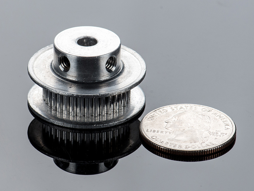
Timing pulleys play a crucial role in CNC (Computer Numerical Control) machines for precise positioning of the tool or workpiece. Here’s an explanation of how timing pulleys are integrated into CNC machines for positioning:
1. Drive System:
In a CNC machine, timing pulleys are often used as part of the drive system. The driving pulley is connected to a motor, typically a stepper motor or a servo motor, which provides rotational power. The driven pulley is connected to the axis or axes responsible for moving the tool or workpiece. The timing belt or chain, meshing with the pulleys, transfers the rotational motion from the motor to the driven pulley, enabling precise positioning.
2. Synchronization:
The primary purpose of timing pulleys in CNC machines is to achieve synchronization between the motor and the axis movement. By using toothed timing belts or chains, the rotational motion from the motor is precisely transferred to the driven pulley. The teeth on the timing belt or chain mesh with the teeth on the pulley, creating a positive engagement that ensures accurate and synchronized movement.
3. Pulley Ratios:
To achieve the desired positioning accuracy, CNC machines often utilize different pulley ratios. By varying the diameter or the number of teeth on the pulleys, the speed and torque of the driven axis can be adjusted. This allows for fine-tuning the positioning performance based on the specific requirements of the CNC application.
4. Multiple Axes:
CNC machines commonly have multiple axes, such as X, Y, and Z axes for three-dimensional movement. Each axis is equipped with its respective timing pulley system. The pulleys and timing belts or chains for each axis are carefully calibrated and synchronized to ensure coordinated movement and precise positioning in all directions.
5. Tensioning and Alignment:
Proper tensioning and alignment of the timing belts or chains are essential for accurate positioning in CNC machines. Adequate tension ensures that the belts or chains maintain the necessary grip and engagement with the pulleys, preventing slippage or backlash. Regular inspection and adjustment of tension and alignment are necessary to maintain optimal positioning performance.
6. Encoder Feedback:
To enhance positioning accuracy, CNC machines often incorporate encoder feedback systems. Encoders provide precise position feedback to the control system, allowing for closed-loop control. The encoder is usually connected to the driven pulley, enabling real-time monitoring and adjustment of the position to ensure accurate positioning during operation.
7. Control System Integration:
The timing pulley systems in CNC machines are integrated into the overall control system. The control software sends commands to the motor, dictating the desired positioning and movement. The control system interprets the input signals, calculates the appropriate motor rotations, and adjusts the timing pulley system to achieve the specified positioning accuracy.
In summary, timing pulleys are integrated into CNC machines for precise positioning by serving as part of the drive system, enabling synchronization between the motor and the driven axis, using pulley ratios to control speed and torque, accommodating multiple axes, ensuring proper tensioning and alignment, incorporating encoder feedback for enhanced accuracy, and integrating with the control system. These mechanisms and considerations work together to achieve the high precision and accuracy required in CNC machining operations.
How does a timing pulley differ from a standard pulley?
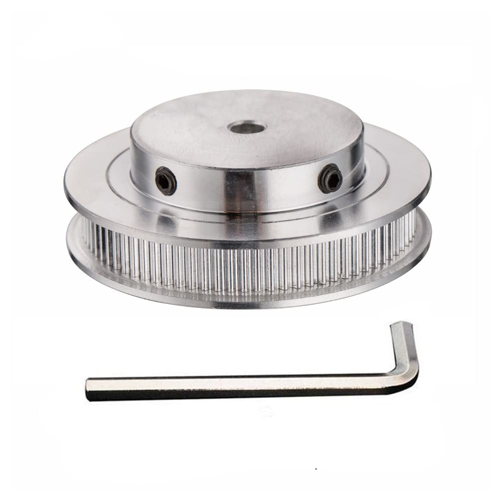
A timing pulley differs from a standard pulley in design and functionality. While both types of pulleys are used in mechanical systems, they serve different purposes and have distinct features. Here’s an explanation of the key differences between a timing pulley and a standard pulley:
1. Toothed Profile:
The most significant difference between a timing pulley and a standard pulley is the presence of teeth on the timing pulley. Timing pulleys have grooves or teeth on their circumferential surface that mesh with corresponding teeth on timing belts. This toothed profile enables positive engagement between the pulley and the belt, providing precise motion and preventing slippage. In contrast, standard pulleys typically have a smooth or V-shaped groove that allows for the use of flat belts or V-belts, which rely on friction for power transmission.
2. Synchronization and Timing:
Timing pulleys are specifically designed for applications that require accurate timing and synchronization. The teeth on the timing pulley mesh with the teeth on the timing belt, creating a positive drive system. This ensures that the rotational motion of the driving pulley is transferred precisely to the driven pulleys, maintaining synchronization and accurate timing. Standard pulleys, on the other hand, do not provide this level of precise timing and are commonly used in applications where synchronization is not critical.
3. Power Transmission:
A timing pulley is primarily used for power transmission in applications that require precise motion control. The positive engagement between the teeth of the timing pulley and the timing belt ensures efficient power transfer without slippage. This is particularly important in applications where accurate speed ratios and torque transmission are necessary. Standard pulleys, while also used for power transmission, rely on friction between the pulley and the belt for power transfer, which may result in some slippage under heavy loads or high speeds.
4. Customization and Configurations:
Timing pulleys offer a wide range of customization options to meet specific application requirements. They can be manufactured with different tooth profiles, pitch sizes, and numbers of teeth to achieve the desired speed ratios and torque transmission. Standard pulleys, on the other hand, have fewer customization options and are generally available in standard sizes and configurations.
5. Maintenance and Reliability:
Timing pulleys and timing belts require less maintenance compared to standard pulleys and belts. The toothed profile of timing pulleys prevents slippage, reducing the need for frequent tension adjustments. Additionally, the positive engagement between the timing pulley and the timing belt ensures reliable power transmission with minimal wear and elongation of the belt.
Overall, the main differences between a timing pulley and a standard pulley lie in their toothed profile, synchronization capabilities, precise timing, customization options, and maintenance requirements. Timing pulleys are specifically designed for applications that demand accurate motion control and synchronization, while standard pulleys are more commonly used where precise timing is not critical.


redaktör av CX
2024-03-27