Archives

admin

February 18, 2021

Regular Grid Spacer and Half Spacer Style Couplings Horizontal Cover
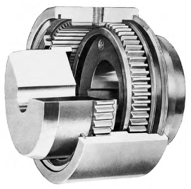
The Grid Spacer coupling is definitely an perfect coupling for applications where there’s a necessity for some vibration dampening in installations that are not close coupled. This implies some level of gap, or BSE exists in between the driver and driven tools shafts.
All Grid Spacer Couplings are provided with Horizontal Split Covers. The split cover design lets for quick entry to your grid spring for ease of upkeep or grid spring replacement. The Horizontal Split Cover is also ideal for applications in which there could be some constraints to the diameter from the coupling.
Capabilities:
Intended for ease of servicing and grid spring substitute
High tensile grid springs make sure superior coupling functionality and longer coupling existence
Split covers make it possible for for easy access to grid springs
Interchangeable with sector conventional grid couplings

Regular Grid Design Couplings Horizontal and Vertical Cover
The Grid coupling is an suitable coupling for applications the place superb efficiency is preferred and further demands for vibration dampening might exist. The Horizontal Split Cover design is suggested in applications wherever there may be some constraints
on the diameter in the coupling. The vertical design and style is advisable for applications exactly where increased speed is probably the necessities.
Attributes:
Created for ease of servicing and grid spring replacement
Higher tensile grid springs assure superior coupling effectiveness and longer coupling lifestyle
Split covers enable for simple access to grid springs
Interchangeable with sector conventional grid couplings

admin

February 18, 2021

The following facts is necessary when generating a Grid coupling selection:
Description of motor or engine, the horse energy (or KW), and RPM at slowest coupling velocity even though beneath load
Description in the driven products
Shaft and keyway sizes plus the type of match for driver and driven equipment (clearance or interference)**
Shaft separation (BSE)
Physical space limitations (see Application Worksheet)
Figure out what the environmental problems is going to be, such as temperature, corrosive conditions, interference from surrounding structures, etc.
By default, sizes 1020 – 1090 might be clearance fit, sizes 1100 – 1200 are going to be interference fit.
** Machines all bores and keyways to meet the dimensional and tolerance specs per ANSI/AGMA 9002-B04 for inch bores, or ISO 286-2 for metric bores.
Normal grid couplings consist of two grid hubs, a grid spring, as well as a cover assembly. When the shaft separation necessitates a spacer type coupling, the coupling will include two shaft hubs, two spacer hubs, a grid spring, and also a horizontal cover assembly.
Formulas Made use of To Determine Torque:
Application Torque (in-lbs) = ( horse energy x 63025 ) /RPM
Application Torque (Nm) = ( horse energy x 9550 ) /RPM
Selection Torque = Application Torque x Support Element
Large Peak Loads and Brake Applications
For applications the place substantial peak loads or large braking torques may be existing, the following additional information and facts might be necessary:
Procedure peak torque and frequency
Duty cycle
Brake torque rating
The variety torque formula is similar to the formula shown over except the application torque must be doubled before applying the support aspect.
Application Torque (in-lbs) = ( horse energy x 63025 ) /RPM
Application Torque (Nm) = ( horse electrical power x 9550 ) /RPM
Choice Torque = two x Application Torque x Services Issue
Steps In Picking out A Grid Coupling
Phase one: Determine the application torque using the formula shown over.
Stage 2: Choose the Services Issue through the charts .
For applications not displayed make use of the chart shown for the suitable. Ascertain the Selection Torque employing the formula proven above.
Stage three: Making use of the assortment torque as calculated, refer to the Performance Chart
Step 4: Review the utmost bore for that size picked and assure the required bore sizes do not exceed the maximum allowable. If the necessary bore dimension is greater, step as much as the next size coupling and test to see when the bore sizes will match.
Phase 5: Applying the picked coupling size, assess the bore and keyway sizes
Stage 6: Speak to your local industrial supplier together with the aspect numbers to location sizes together with the charts for UPC part numbers.

admin

February 18, 2021

The Electrical power of Torsional Dampening
Our grid fashion coupling design and style has demonstrated its capacity to dampen vibration by as much as 30% and will cushion shock loads that can trigger injury to the two the driving and driven equipment. The tapered grid spring design absorbs effect vitality by spreading the power out more than the complete length of the grid spring hence cutting down the magnitude from the torque spikes.
The Our style and design utilizes a curved hub tooth profile which generates a progressive get in touch with with all the versatile grid spring since the application torque increases. This feature presents a much more helpful and efficient transmission of power in correctly aligned couplings.
Our versatile design and style of marketplace standard hubs and grid springs
for both horizontal and vertical cover styles enable Our couplings
to get interchangeable with other marketplace regular grid couplings and elements.
Good grid coupling installation and upkeep can include to a longer coupling lifestyle. Grid spring replacement is easy and will be carried out at a fraction of the expense and time of the complete coupling.
Attributes
Substantial tensile, shot-peened alloy steel grid springs and precision machined hubs assure superior coupling performance and prolonged daily life.
Grid couplings with tapered grids are intended to become interchangeable with other field normal grid couplings with each horizontal and vertical grid covers.
Grid couplings are designed for ease of set up and maintenance reducing labor and downtime prices.
The torsional flexibility and resilience of grid couplings assists reduce vibration and cushions shock and impact loads.
Cover fasteners is often presented in either Inch or Metric sizes.
Outstanding for use in applications the place the equipment is near coupled or spaced apart requiring a spacer style coupling arrangement.
Stock spacer types are available or requests for custom spacer lengths can be addressed by engineering.
Horizontal Split Cover Style and design
Suitable for limited space
Makes it possible for simple accessibility for the grid spring
Effectively suited for reversing applications
Light-weight die-cast aluminum grid cover
Vertical Split Cover Design
Ideal for larger working speeds
Lets simple entry towards the grid spring
Cover is produced from stamped steel for strength
Complete Spacer Layout ¡§C Horizontal Cover
Drop-out style and design great for pump applications and servicing
Stock sizes 1020 thru 1090
Lightweight die-cast aluminum grid cover
Half Spacer Style ¡§C Horizontal Cover
Provides extra BSE dimensions
Lightweight die-cast aluminum grid cover

admin

February 5, 2021

Why Coupling Grease?
Ample lubrication is crucial for satisfactory gear coupling operation. Gear Coupling Grease is specifically designed for gear coupling applications to boost coupling life whilst significantly decreasing maintenance time. Its higher viscosity base oil and tackifier mix to maintain the grease in location and avoid separation and it can be in total compliance with NSI/AGMA 9001-B97 lubrication suggestions.
Coupling Grease is dark brown in color and produced with a lithium soap/polymer thickener, which has superior resistance to oil separation when subjected to large centrifugal forces normally discovered in couplings. Bearing or general goal greases have a tendency to separate and get rid of effectiveness because of large centrifugal forces about the a variety of substances at high rotational speeds. These higher centrifugal forces encountered in couplings separate the base oil from your thickeners. Hefty thickeners, which have no lubrication attributes, accumulate within the gear tooth mesh area leading to premature coupling failure. Gear Coupling Grease is intended to extremely resistant to centrifugal separation in the oil and thickener, which lets the lubricant to get applied to get a fairly lengthy period of time.
One of many secrets towards the achievement of Gear Coupling Grease would be the variable consistency throughout the working cycle in the application. The consistency of our gear coupling grease modifications using the operating problems. Working with the lubricant underneath actual service problems leads to the grease to turn out to be semi-fluid, functionally solash lubricating the put on surfaces with the coupling. Because the grease cools, it returns towards the original consistency, thereby stopping leakage.
Gear Coupling Grease is obtainable from stock in 14 oz. cartridges, 1 lb. and five lb. cans.
Options
Minimizing of coupling put on
Resistance to water washing
Corrosion and rust protection
Higher load carrying abilities
Extended relubrication frequency
Use at temperatures up to 325° F
Staying in location under large speeds
Resistance to centrifugal separation
Reduction in down time & upkeep cost
Gear Coupling Grease has a consistency which overlaps the NLGI grades 0 and one. This grease is specially formulated by using a lithium/polymer thickener and fortified with corrosion, oxidation, extreme pressure, and a effective rust inhibitor additive package.

admin

February 5, 2021

Restricted Finish Float Spacer Variety
The addition of plates restricts axial travel for the drive or driven shaft. The spacer helps make it feasible to get rid of the hubs from both shaft without the need of disturbing the connected units.
Vertical Floating Shaft Sort
The reduced coupling features a hardened crowned button inserted while in the plate in the decrease hub. The whole floating assembly rest on the button. Optional development on the upper coupling will be a rigid hub to the floating shaft by using 
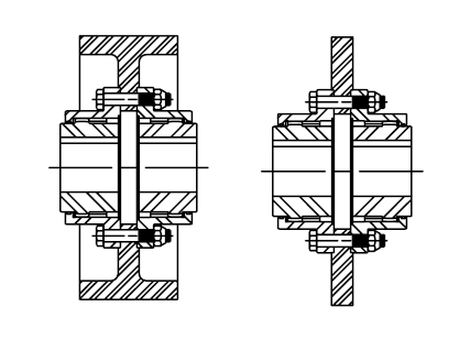
a flex half within the top rated.
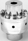
Vertical Style
This coupling has the identical horsepower, RPM and misalignment abilities as the regular couplings of corresponding sizes. A plate which has a hardened crowned button rests on the reduce shaft which supports the fat from the sleeve.
Insulated Form
Use of a non-metallic materials involving flanges and all around the bolts prevents any stray currents from a single shaft for the other.
Jordan Form
Applied on Jordan machines and refiners, this design is very similar to the slide type coupling except the long hub is split and secured towards the shaft by using a bolt clamp. This permits swift axial adjustment of the Jordan shafts i this hub.
Engineered Shear Pin Type
Shear pin couplings are mainly applied to limit transmitted torque to a redetermined load. THis in flip disconnectes the driver and driven shafts if torque exceeds the specified limits. They’re primarily suited to safeguard gear when jams take place. Components are re-useable just after pins shear. The coupling will retain lubricant for any quick time period to permit tools to become shut down.
Brakewheel and Brake Disc Variety
Replaceable brakewheel and brake disc piloted around the outdoors diameter of a typical sleeve and/or rigid hub. Provides a preference of applying braking energy to the load or driving motor.
Double Engagement Half Gear Form
Both internal and external teeth in the single sleeve. Is often bolted to a rotating flywheel, shaft or drum to connect driver or driven machine with a shaft extension. This coupling has the exact same capabilities, ratings and misalignment capability as the regular group of couplings.
Rigid Alloy Steel FARR Style
Male/Female piloted rigid coupling coupling with keeper plates. This coupling is made use of whenever a rigid connection is required concerning the reduced pace shaft of the gearbox as well as the head shaft of the conveyor, bucket elevator, mixer or any overhung or suspended load.

admin

February 5, 2021

RA and RAHS Type Rigid Adjustable Couplings
The RA and RAHS couplings are provided in two unique styles. Form II coupling includes two rigid hubs, adjusting nut and split ring and split ring for motor bub. Type IV coupling consists of two rigid hubs, adjusting nut, split ring for motor hub and spacer.
Functions
Axial positioning of your pump impeller in vertical pump applications
Clearence match bores will allow for uncomplicated set up and maintenance for pump and/or motor
Quickly adjustable for vertical clearence
Removable spacer for quick servicing
AISI 1045 Steel
Stainless Steel coupling also accessible
Ordering Information
Application: Driver and Driven.
Energy: Motor horspower or torque requirement.
Pace: Motor Pace or Driven RPM.
Distance in between shaft ends (BSE).
Shaft sizes.
Adjusting nut threads.
Quantity of believe in on either or each shafts.
Submit drawing if accessible.

admin

February 3, 2021

FSL Type Slide Coupling
The FSL Style coupling consists of 1 or two modified flex hubs determined by the maximum slide essential, two sleeves, a single plate with lube holes and a single accessory kit. The coupling is provided with exposed bolts as regular. Shrouded bolts are available on request by way of dimension 5.five.
Functions
For prolonged lifestyle
Common 20?? strain angle
Heat treated bolts for better strength
Corrosion resistant bolts and nuts for ease of upkeep
Assembled to suit a wide selection of axial movement
Plates with lube holes so both halves of the coupling will be adequately lubricated
Ordering Facts
Application: Driver and Driven.
Kind and dimension of coupling, horizontal, vertical etc.
Energy: Motor horspower or torque requirement.
Speed: Motor RPM or Driven RPM.
Distance involving shaft ends (maximum-minimum shaft separation).
Shaft sizes.
Quantity of slide demanded.

FMM Variety Mill Motor Couplings
The FMM Sort coupling consists of a single normal flex hub, 1 universal straight bored hub as common, two sleeves and one particular accessory kit. This coupling is supplied with exposed bolts as normal. Shrouded bolts are available on request by means of dimension 5.5.
Features
For lengthy life
Regular 20?? strain angle
Heat handled bolts for higher strength
Corrosion resistant bolts and nuts for ease of upkeep
Supplies parallel, angular misalignment and end float
Flex Half coupling interchangeable with market specifications
Long Universal Hub made use of for AISE Motor Frames
Ordering Information
Application: Driver and Driven.
Kind and dimension of coupling, horizontal, vertical and so forth.
Electrical power: Motor horspower or torque requirement.
Speed: Motor RPM or Driven RPM.
Distance in between shaft ends (BSE).
Shaft sizes.
Mill Motor frame dimension.
Submit a drawing if available.

admin

February 2, 2021

FHDFS Variety Floating Shaft Couplings
The FHDFS Style coupling consists of two flex-rigid couplings and one floating shaft. The coupling is provided using the rigid hubs outboard except if otherwise specified. The coupling includes exposed bolts only.
Attributes
Flex Hubs for prolonged life
Conventional 20° strain angle
Heat handled bolts for greater strength
Corrosion resistant bolts and nuts for ease of maintenance
Accommodates parallel and angular misalignment
Removal of center assembly permits forease of servicing with out repositioning machinery
Rigid hubs outboard lets for greater shaft diameters
Made for high-torque low-speed applications that arise in mill operations
Ordering Information
Application: Driver and Driven.
Sort and dimension of coupling, horizontal, vertical and so on.
Electrical power: Motor horspower or torque requirement.
Speed: Motor RPM or Driven RPM.
Distance amongst shaft ends (BSE).
Connecting tools shaft sizes.
Specify which hubs are to become utilised to the products (Rigid or Flex).
Rigid hubs might be utilized about the tools unless of course otherwise specified.
Length of floating shaft may possibly affect max angular misalignment.

FMM Type Mill Couplings
The FMM Kind coupling includes one typical flex hub, 1 universal straight bored hub as common, two sleeves and one particular accessory kit. This coupling is provided with exposed bolts as common. Shrouded bolts are available on request by size five.5.
Attributes
For long lifestyle
Typical 20° strain angle
Heat treated bolts for greater strength
Corrosion resistant bolts and nuts for ease of servicing
Gives parallel, angular misalignment and finish float
Flex Half coupling interchangeable with business specifications
Long Universal Hub supplied to client specifications with straight or tapered bores
Ordering Information and facts
Application: Driver and Driven.
Style and dimension of coupling, horizontal, vertical and so forth.
Electrical power: Motor horspower or torque necessity.
Pace: Motor RPM or Driven RPM.
Distance amongst shaft ends (BSE).
Shaft sizes.
Taper per foot and length of taper if tapered bore is required.
Specify counterbore dimensions if sought after.
Submit a drawing if obtainable.

admin

February 2, 2021

FHDFR Type Flex-Rigid Couplings
The FHDFR Sort coupling includes 1 flex hub, one particular sleeve with bolt-on seal carrier, 1 rigid hub and one particular accessory kit. This coupling is supplied with exposed bolts only.
Options
For lengthy daily life
Normal 20° pressure angle
Heat treated bolts for higher strength
Corrosion resistant bolts and nuts for ease of upkeep
Presents parallel, angular misalignment and end float
Developed for high-torque low-speed applications that happen in mill operations
Ordering Details
Application: Driver and Driven.
Style and dimension of coupling, horizontal, vertical and so on.
Energy: Motor horspower or torque requirement.
Speed: Motor RPM or Driven RPM.
Distance amongst shaft ends (BSE).
Shaft sizes.

FHD Form Flex-Flex Couplings
The FHD Variety coupling consists of two flex hubs, two sleeves with bolt-on seal carriers and
one accessory kit. This coupling is supplied with exposed bolts only.
Features
For long daily life
Conventional 20° pressure angle
Heat handled bolts for better power
Corrosion resistant bolts and nuts for ease of maintenance
Provides parallel, angular misalignment and end float
Built for high-torque low-speed applications that take place in mill operations
Ordering Information and facts
Application: Driver and Driven.
Variety and dimension of coupling, horizontal, vertical etc.
Electrical power: Motor horspower or torque requirement.
Speed: Motor RPM or Driven RPM.
Distance concerning shaft ends (BSE).
Shaft sizes.

admin

February 2, 2021

FFS Floating Shaft Gear Coupling
The FFS Type coupling includes two flex-rigid couplings and 1 floating shaft. This coupling is supplied with rigid hubs outboard unless of course otherwise specified. Exposed bolts are conventional. Shrouded bolts are available on request tru sizes 5.five.
Options
Flex Hubs for prolonged lifestyle
Normal 20 pressure angle
Heat handled bolts for higher power
Corrosion resistant bolts and nuts for ease of upkeep
Accommodates angular, parallel, and axial misalignment
Removal of center assembly permits for ease of upkeep with out repositioning machinery
Rigid hubs outboard permits for more substantial shaft diameters
Ordering Information and facts
Application: Driver and Driven.
Type and dimension of coupling, horizontal, vertical and so forth.
Electrical power: Motor horspower or torque requirement.
Speed: Motor RPM or Driven RPM.
Distance among shaft ends (BSE).
Equipment shaft sizes.
Specify which hubs are for being made use of over the tools (Rigid or Flex).
Rigid hubs will probably be utilized about the equipment unless otherwise specified.

FFR Single Engagement (Flex-Rigid)
The FRR Variety coupling consists of one flex hub, 1 rigid hub, one particular sleeve and one particular accessory kit. This coupling is supplied with exposed bolts as common. Shrouded bolts can be found upon request by size five.5.
Characteristics
Flex Hub for long lifestyle
Regular 20 stress angle
Heat treated bolts for better strength
Corrosion resistant bolts and nuts for ease of upkeep
Accommodates angular misalignment only
Half coupling interchangeable with marketplace requirements
Ordering Information and facts
Application: Driver and Driven.
Kind and size of coupling, horizontal, vertical and so on.
Energy: Motor horspower or torque necessity.
Speed: Motor RPM or Driven RPM.
Distance in between shaft ends (BSE).
Shaft sizes.