

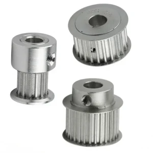
Polia de sincronização EP-L100 de 9,525 mm com furo reto em aço e ferro fundido
A EP-L100 é uma polia de sincronização com furo reto, fabricada de acordo com o padrão da Série L, com um passo nominal de 9,525 mm e uma largura de correia de referência de 100 (1 polegada). Esta série abrange números de dentes de 10 a 120, oferecendo uma das mais amplas gamas de seleção disponíveis em uma única família de polias de sincronização com passo L. O diâmetro primitivo da série varia de 30,32 mm no modelo de 10 dentes até 363,83 mm na variante de 120 dentes, tornando-a adequada tanto para projetos de máquinas compactas quanto para sistemas de transmissão de potência com grande distância entre centros, onde é necessária uma polia de sincronização com padrões dimensionais consistentes.
Disponível em dois materiais — aço para a faixa de 10 a 48 dentes e ferro fundido para 49 dentes ou mais — a polia sincronizadora de furo reto L100 é usinada com um furo passante limpo que permite acabamento personalizado de acordo com o diâmetro exato do eixo especificado pelo usuário. O diâmetro do furo (d) é padronizado em 8 mm para as variantes menores, aumentando para 11 mm para a faixa intermediária de dentes e chegando a 14 mm para os modelos em ferro fundido, acomodando uma ampla gama de tamanhos de eixos usados em máquinas industriais sem a necessidade de bucha cônica ou outro elemento intermediário no cubo. As configurações de flange incluem 6F (com flange), 6WF (com flange larga), 6W (com flange larga sem flange) e 6A (com flange larga sem flange em ferro fundido), proporcionando flexibilidade para atender aos requisitos de alinhamento da correia e aos ambientes de aplicação.
Série de polias de distribuição | Polia de distribuição com furo reto disponível nas proximidades
EP-L100 9,525 mm Aço e Ferro Fundido
Polia de distribuição com furo reto | Polia da correia de distribuição
Uma máquina de precisão polia de sincronização de furo reto Na Série L (passo de 9,525 mm), disponível em aço e ferro fundido, com 10 a 120 dentes. Projetada para transmissões por correia sincronizadas em aplicações de automação, embalagem, transporte e transmissão de potência em todo o mundo.
1. Especificações Técnicas — Série L100 (Passo de 9,525 mm) Polia de sincronização de furo reto
A tabela abaixo contém as especificações dimensionais completas para todos os modelos padrão do EP-L100. polia de sincronização de furo reto Série. As dimensões estão em milímetros. Dp = Diâmetro primitivo, De = Diâmetro externo, Df = Diâmetro da flange, Dm = Diâmetro do cubo, Di = Diâmetro interno da flange, F = Largura da correia, L = Largura do cubo, d = Diâmetro do furo. polia de sincronização de furo reto está disponível para engenheiros que buscam um polia de sincronização de furo reto próxima Com estoque global e capacidade de despacho rápido.
| Código da peça | Dentes | Tipo | Material | Dp (mm) | De (mm) | Df (mm) | Dm (mm) | Diâmetro (mm) | F (mm) | L (mm) | d (mm) |
|---|---|---|---|---|---|---|---|---|---|---|---|
| 10 L 100 | 10 | 6F | Aço | 30.32 | 29.56 | 37 | 20 | – | 31.8 | 45 | 8 |
| 11 L 100 | 11 | 6F | 33.35 | 32.59 | 37 | 22 | – | 31.8 | 45 | 8 | |
| 12 L 100 | 12 | 6F | 36.38 | 35.62 | 43 | 24 | – | 31.8 | 45 | 8 | |
| 13 L 100 | 13 | 6F | 39.41 | 38.65 | 44 | 28 | – | 31.8 | 45 | 8 | |
| 14 L 100 | 14 | 6F | 42.45 | 41.68 | 48 | 28 | – | 31.8 | 45 | 11 | |
| 15 L 100 | 15 | 6F | 45.48 | 44.72 | 51 | 34 | – | 31.8 | 45 | 11 | |
| 16 L 100 | 16 | 6F | 48.51 | 47.75 | 54 | 36 | – | 31.8 | 45 | 11 | |
| 17 L 100 | 17 | 6F | 51.54 | 50.78 | 57 | 36 | – | 31.8 | 45 | 11 | |
| 18 L 100 | 18 | 6F | 54.57 | 53.81 | 60 | 40 | – | 31.8 | 45 | 11 | |
| 19 L 100 | 19 | 6F | 57.61 | 56.84 | 64 | 40 | – | 31.8 | 45 | 11 | |
| 20 L 100 | 20 | 6F | 60.64 | 59.88 | 66.5 | 40 | – | 31.8 | 45 | 11 | |
| 21 L 100 | 21 | 6F | 63.67 | 62.91 | 70 | 45 | – | 31.8 | 45 | 11 | |
| 22 L 100 | 22 | 6F | 66.70 | 65.94 | 75 | 45 | – | 31.8 | 45 | 11 | |
| 23 L 100 | 23 | 6F | 69.73 | 68.97 | 79 | 55 | – | 31.8 | 45 | 11 | |
| 24 L 100 | 24 | 6F | 72.77 | 72.00 | 79 | 55 | – | 31.8 | 45 | 11 | |
| 25 L 100 | 25 | 6F | 75.80 | 75.04 | 82.5 | 58 | – | 31.8 | 45 | 11 | |
| 26 L 100 | 26 | 6F | 78.83 | 78.07 | 86 | 58 | – | 31.8 | 45 | 11 | |
| 27 L 100 | 27 | 6F | 81.86 | 81.10 | 86 | 58 | – | 31.8 | 45 | 11 | |
| 28 L 100 | 28 | 6F | 84.89 | 84.13 | 91 | 58 | – | 31.8 | 45 | 11 | |
| 29 L 100 | 29 | 6F | 87.93 | 87.16 | 94 | 58 | – | 31.8 | 45 | 11 | |
| 30 L 100 | 30 | 6F | 90.96 | 90.20 | 97 | 70 | – | 31.8 | 45 | 11 | |
| 32 L 100 | 32 | 6F | 97.02 | 96.26 | 102 | 70 | – | 31.8 | 45 | 11 | |
| 33 L 100 | 33 | 6F | 100.05 | 99.29 | 106 | 70 | – | 31.8 | 45 | 11 | |
| 34 L 100 | 34 | 6F | 103.08 | 102.32 | 112 | 70 | – | 31.8 | 45 | 11 | |
| 35 L 100 | 35 | 6F | 106.12 | 105.35 | 112 | 70 | – | 31.8 | 45 | 11 | |
| 36 L 100 | 36 | 6F | 109.15 | 108.39 | 115 | 70 | – | 31.8 | 45 | 11 | |
| 40 L 100 | 40 | 6WF | 121.28 | 120.51 | 128 | 70 | 100 | 31.8 | 45 | 11 | |
| 41 L 100 | 41 | 6WF | 124.31 | 123.55 | 135 | 70 | 103 | 31.8 | 45 | 11 | |
| 42 L 100 | 42 | 6WF | 127.34 | 126.58 | 135 | 70 | 106 | 31.8 | 45 | 11 | |
| 44 L 100 | 44 | 6WF | 133.40 | 132.64 | 142 | 70 | 112 | 31.8 | 45 | 11 | |
| 45 L 100 | 45 | 6WF | 136.44 | 135.67 | 142 | 70 | 115 | 31.8 | 45 | 11 | |
| 47 L 100 | 47 | 6WF | 142.50 | 141.74 | 150 | 70 | 121 | 31.8 | 45 | 11 | |
| 48 L 100 | 48 | 6WF | 145.53 | 144.77 | 150 | 70 | 124 | 31.8 | 45 | 11 | |
| 49 L 100 | 49 | 6W | Ferro fundido | 148.56 | 147.80 | – | 70 | 127 | 31.8 | 45 | 14 |
| 50 L 100 | 50 | 6W | 151.60 | 150.83 | – | 70 | 130 | 31.8 | 45 | 14 | |
| 52 L 100 | 52 | 6W | 157.66 | 156.90 | – | 70 | 136 | 31.8 | 45 | 14 | |
| 56 L 100 | 56 | 6W | 169.79 | 169.02 | – | 70 | 149 | 31.8 | 45 | 14 | |
| 57 L 100 | 57 | 6W | 172.82 | 172.06 | – | 70 | 152 | 31.8 | 45 | 14 | |
| 60 L 100 | 60 | 6W | 181.91 | 181.15 | – | 75 | 160 | 31.8 | 50 | 14 | |
| 65 L 100 | 65 | 6A | 197.07 | 196.31 | – | 75 | 176 | 31.8 | 50 | 14 | |
| 66 L 100 | 66 | 6A | 200.11 | 199.34 | – | 75 | 179 | 31.8 | 50 | 14 | |
| 72 L 100 | 72 | 6A | 218.30 | 217.53 | – | 75 | 197 | 31.8 | 50 | 14 | |
| 84 L 100 | 84 | 6A | 254.68 | 253.92 | – | 75 | 233 | 31.8 | 50 | 14 | |
| 90 L 100 | 90 | 6A | 272.87 | 272.11 | – | 75 | 252 | 31.8 | 50 | 14 | |
| 96 L 100 | 96 | 6A | 291.06 | 290.30 | – | 75 | 269 | 31.8 | 50 | 14 | |
| 120 L 100 | 120 | 6A | 363.83 | 363.07 | – | 75 | 342 | 31.8 | 50 | 14 |
Todas as dimensões em mm. F = referência de largura da correia. L = comprimento do cubo. Df aplica-se apenas aos tipos com flange. Di aplica-se apenas aos tipos com flange larga. O número da flange (código de largura da correia correspondente) foi omitido por brevidade; consulte o catálogo para obter a especificação da correia correspondente.
2. Cinco principais vantagens do produto
Com opções de 10 a 120 dentes sob a mesma estrutura de código de peça L100, esta série L100 permite que os engenheiros especifiquem a relação de velocidade exata de que precisam sem precisar trocar para uma família de passo diferente. Seja para uma aplicação que exige uma posição de acionamento compacta de 10 dentes para um transportador servoacionado ou uma roda motriz de 120 dentes para uma mesa indexadora de baixa velocidade, a polia sincronizadora de furo reto L100 oferece precisão de passo consistente em toda a faixa, simplificando a padronização do projeto e reduzindo a complexidade do estoque de peças de reposição em instalações industriais em todo o mundo.
A construção em aço (de 10 a 48 dentes) proporciona alta resistência à tração, excelente usinabilidade para acabamento do furo e desempenho confiável em aplicações de acionamento dinâmicas e de alto ciclo. O ferro fundido (de 49 a 120 dentes) oferece as características de amortecimento e a massa necessárias para estabilizar diâmetros maiores. polia de sincronização de furo reto unidades contra erro de passo induzido por vibração no ponto de engrenamento da correia dentada. A adequação do material à quantidade de dentes — e, portanto, à provável carga de torque — é uma prática padrão de engenharia, e a divisão de materiais do L100 reflete essa lógica diretamente.
O L100 polia de sincronização de furo reto A série oferece quatro códigos de flange distintos — 6F, 6WF, 6W e 6A — cada um adequado a diferentes requisitos de alinhamento da correia e folga da carcaça. Uma polia de sincronização com furo reto e flange (6F, 6WF) mantém a correia de sincronização de passo L centrada na face da polia sem a necessidade de guias de correia externas, reduzindo a oscilação lateral da correia, especialmente em máquinas de estrutura aberta. As variantes de polia de sincronização com furo reto sem flange (6W, 6A) são preferidas quando um trilho guia fixo ou carcaça fornece restrição lateral, ou quando o sistema de acionamento exige fácil remoção da correia sem desmontar a polia do eixo.
O passo de 9,525 mm da Série L é um dos passos de correia dentada padrão mais amplamente adotados em máquinas industriais em todo o mundo, reconhecido tanto pelo sistema imperial (Série L) quanto pelo sistema métrico intercambiável em polegadas. Correias e polias de distribuição As correias da série L100 são compatíveis diretamente com correias de perfil L de qualquer fornecedor importante que atenda aos padrões ANSI/RMA ou equivalentes, garantindo que a substituição da correia nunca dependa de uma única fonte de fornecimento. Essa ampla disponibilidade de correias torna a L100 uma excelente opção. polia de sincronização de furo reto A escolha prática para equipes de manutenção globais que precisam de um produto intercambiável e disponível em estoque.
Ao contrário das variantes de bucha cônica ou de engate rápido, o polia de sincronização de furo reto O produto chega com um furo passante pré-usinado em tamanho padrão, que o usuário final ou sua oficina mecânica pode alargar, mandrilar ou fresar chavetas para o ajuste preciso do eixo necessário. Essa flexibilidade elimina a necessidade de especificar um tamanho de furo final no momento do pedido, reduzindo significativamente o prazo de entrega e tornando o L100 uma opção viável. polia de sincronização de furo reto O SKU de estoque preferencial para distribuidores que atendem a múltiplas aplicações de clientes a partir de um único estoque.
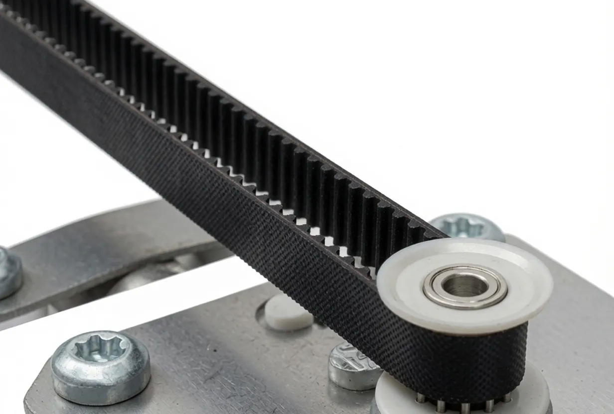
3. Princípio de funcionamento da polia de distribuição de furo reto L100
UM polia de sincronização de furo reto Na série L100, a transmissão de potência ocorre por meio do engrenamento preciso entre os dentes trapezoidais usinados com precisão na face da polia e os perfis de dente correspondentes na superfície interna de uma correia de distribuição da série L. Ao contrário de uma polia em V ou de uma polia plana, onde a transferência de potência depende do atrito e da tensão da correia, a transmissão por correia de distribuição depende inteiramente do engrenamento dos dentes, o que significa que não há deslizamento entre a polia e a correia. Cada rotação da polia motora de distribuição com furo reto produz uma rotação exata e previsível da polia movida — a característica que define uma correia de distribuição. sistema de transmissão por correia sincronizada.
No coração da série L100 está o passo de 9,525 mm. Esse passo — a distância linear do centro de um dente ao centro do próximo, medida ao longo da linha primitiva da correia — determina quantos dentes da correia engatam por revolução e, portanto, rege a relação entre a velocidade da correia e a velocidade da superfície da polia. O diâmetro primitivo (Dp) dessa correia é definido por sua relação entre a velocidade da correia e a velocidade da superfície da polia. polia de sincronização de furo reto O diâmetro externo (De) é calculado a partir da contagem de dentes e do passo usando a fórmula Dp = (N × P) / π, onde N é o número de dentes e P é o passo (9,525 mm). O diâmetro externo (De) é sempre ligeiramente menor que o diâmetro primitivo porque a linha de passo da correia fica acima da raiz do dente, e não na superfície mais externa da polia.
Quando o motor de acionamento gira o eixo de entrada, o torque é transmitido através do encaixe por interferência ou chaveta entre o eixo e o furo da polia sincronizadora de furo reto. Os dentes da polia sincronizadora de furo reto puxam os dentes da correia para a frente no lado da transmissão, e os dentes da correia engatam nos dentes da polia sincronizadora de furo reto acionada na outra extremidade do anel da correia. Como as correias sincronizadoras de passo L são feitas com cordas de tensão de fibra de vidro ou Kevlar que resistem ao alongamento sob carga, a distância entre os centros das polias permanece estável durante toda a operação, evitando a variação de velocidade que ocorreria com uma correia que se estica elasticamente. Essa combinação de geometria dos dentes e rigidez das cordas confere à correia um comportamento dinâmico e estável. polia de sincronização de furo reto impulsionar seu desempenho síncrono de deslizamento zero, que define o que é o sistema de transmissão por correia sincronizada.
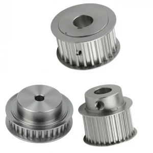
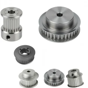
4. Composição do material — Polia de sincronização de furo reto em aço e ferro fundido
Seleção de materiais no L100 polia de sincronização de furo reto A série é determinada pelo diâmetro e, portanto, pelos requisitos de massa e torque da faixa de número de dentes. Polias menores, com diâmetros de passo compactos, operam em velocidades de rotação mais altas para uma determinada velocidade da correia, e as forças centrífugas e de engrenamento dos dentes estão bem dentro da capacidade do aço, sem a necessidade do benefício de amortecimento de massa do ferro fundido. Polias de diâmetro maior, operando em velocidades de rotação mais baixas, suportam cargas de torque mais altas e se beneficiam da absorção de vibração inerente e da dureza superficial do ferro fundido, o que reduz a tendência a ruídos de vibração no ponto de engrenamento dente-correia durante as inversões de direção.
Polia de sincronização de aço (10 a 48 dentes) com furo reto
O aço carbono com resistência à tração tipicamente na faixa de 500–700 MPa proporciona excelente usinabilidade para fresamento de dentes de precisão e acabamento de furos com tolerâncias rigorosas. polia de sincronização de furo retoO corpo em aço é compatível com todos os processos padrão de fresagem de chaveta, alargamento de furo e instalação com parafuso de fixação. Os acabamentos de superfície podem incluir óxido preto, fosfato de zinco ou laca transparente, dependendo do ambiente de operação. A construção em aço com furo reto da polia sincronizadora também torna essas unidades adequadas para aplicações que exigem que as dimensões padrão da polia sincronizadora se adaptem a eixos de aço inoxidável por meio de ajustes de transição apropriados.
Polia de sincronização de ferro fundido (49–120 dentes) com furo reto
Ferro fundido cinzento (normalmente de grau 250 ou equivalente) é usado para coroas com maior número de dentes. polia de sincronização de furo reto variantes. A microestrutura de grafite em flocos do ferro fundido proporciona amortecimento natural da vibração transmitida pela correia de distribuição, e a maior densidade contribui para um funcionamento mais suave em baixas rotações, típicas de polias de distribuição de furo reto de grande diâmetro. O ferro fundido também é inerentemente resistente ao engripamento, tornando-o um material prático para polias que precisam ser desmontadas e reinstaladas em um eixo diversas vezes em situações de manutenção em campo — uma consideração importante para usuários que encomendam esse tipo de polia. polias métricas de correia de distribuição para estoque de manutenção.
5. Guia de Seleção de Polias de Distribuição com Furo Reto — Série L100
Selecionar o correto polia de sincronização de furo reto A partir da gama L100, a configuração inicial considera três parâmetros: número de dentes para a relação de velocidade necessária, material baseado na carga de torque e no ciclo de trabalho, e tipo de flange baseado na guia lateral da correia disponível no projeto da máquina. Engenheiros que já especificaram anteriormente polias métricas de correia de distribuição Em projetos de máquinas europeias, deve-se observar que o passo L100 (9,525 mm) é um padrão em polegadas, e não um padrão métrico — ele é compatível com correias da série L de todos os principais fornecedores, mas não é intercambiável com polias métricas T5 (passo de 5 mm) ou AT5, que usam uma geometria de dente diferente.
Para calcular a relação de transmissão usando este método polia de sincronização de furo retoA relação de velocidade é igual ao número de dentes da polia sincronizadora de furo reto movida dividido pelo número de dentes da polia sincronizadora de furo reto motora. Uma polia motora de 20 dentes combinada com uma polia sincronizadora de furo reto movida de 60 dentes produz exatamente uma redução de velocidade de 3:1. O diâmetro primitivo de qualquer polia sincronizadora de furo reto na tabela pode ser usado para calcular a distância mínima entre centros e o comprimento necessário da correia usando fórmulas padrão de projeto de transmissão por correia sincronizadora disponíveis junto aos fabricantes de correias. A largura uniforme da face da correia F = 31,8 mm em toda a gama de polias sincronizadoras de furo reto simplifica a aquisição da correia: uma única largura de correia (L 100 = 1 polegada de largura) cobre todos os números de dentes da série.
Para compradores que procuram um polia de sincronização de furo reto próxima Para quem precisa de estoque imediato em vez de produção com prazo de entrega, nossa linha padrão L100, com 14 a 36 dentes em aço e 50 a 72 dentes em ferro fundido, geralmente está disponível para envio rápido. polias de correia de distribuição personalizadas Nossa capacidade abrange diâmetros de furo não padronizados, modificações no comprimento do cubo e tratamentos de superfície especiais para qualquer tipo de roda. polia de sincronização de furo reto na série L100 — proporcionando flexibilidade para aplicações OEM que não podem usar o furo padrão pré-usinado.
6. Cenários de aplicação para a polia de distribuição de furo reto L100
O L100 polia de sincronização de furo reto é implantado em uma ampla gama de sistema de transmissão por correia sincronizada aplicações globalmente. Os seguintes representam os contextos de implantação mais comuns para isso. polia de sincronização de furo reto série.
Automação Industrial e Máquinas CNC
Roteadores CNC, cortadoras a laser e sistemas de automação multieixos exigem um posicionamento preciso dos eixos, repetível em frações de milímetro. O engate síncrono sem deslizamento da série L sistema de transmissão por correia sincronizada — com o L100 polia de sincronização de furo reto Em sua essência, proporciona a repetibilidade posicional exigida por esses sistemas. O passo de 9,525 mm oferece um bom equilíbrio entre as dimensões compactas da polia de acionamento e a quantidade de dentes necessária para um engate suave de múltiplos dentes ao longo do arco de contato na polia de acionamento, reduzindo a carga por dente e prolongando a vida útil da correia em ambientes de automação de alta frequência.
Linhas de embalagem e processamento de alimentos
As máquinas de embalagem dependem de transmissões por correia sincronizadas para coordenar o tempo de alimentação do filme, ativação da mandíbula de selagem e indexação do produto. Qualquer deslizamento entre as posições das polias motora e movida resulta diretamente em posições de selagem desalinhadas, desperdício de filme ou produto rejeitado. O modelo L100 polia de sincronização de furo reto A série é amplamente utilizada em máquinas de formação, enchimento e selagem, linhas de embalagem e equipamentos de encaixotamento em fábricas de embalagens na Europa e na América do Norte. A configuração de furo reto permite a rápida integração em eixos de acionamento existentes durante as trocas de linha, sem a necessidade de remoção das buchas de fixação cônica, o que reduz o tempo de inatividade.
Sistemas de transporte e movimentação de materiais
Sistemas de transporte que manuseiam produtos que exigem sincronização precisa — como o manuseio de cargas unitárias em centros de distribuição, zonas de acumulação de produtos ou transportadores inclinados em mineração e processamento de agregados — utilizam sistemas de acionamento por correia dentada com passo em L, onde a posição do produto deve acompanhar exatamente o movimento da superfície da correia. A correia de ferro fundido de maior diâmetro polia de sincronização de furo reto As variantes da série L100, com dimensões Di de até 342 mm no modelo de 120 dentes, são adequadas para aplicações de acionamento principal de baixa velocidade e alto torque encontradas em cabeçotes de correias transportadoras de serviço pesado em operações de mineração australianas e instalações de processamento agrícola sul-americanas.
Máquinas de Impressão e Manuseio de Papel
Impressoras, máquinas de corte e vinco e linhas de dobra de papel utilizam amplamente transmissões por correia dentada para coordenar múltiplos eixos que devem permanecer em sincronia precisa durante todo o ciclo de impressão. O passo da série L polia de sincronização de furo reto Proporciona a sincronização repetível entre o cilindro de impressão, os rolos de tinta e o mecanismo de alimentação de papel, o que possibilita um registro de impressão consistente em altas velocidades. Fabricantes de máquinas de impressão na Alemanha, Japão e Estados Unidos frequentemente especificam o L100. polia de sincronização de furo reto Unidades para projetos de eixos de acionamento em equipamentos de impressão comerciais e industriais.
Equipamentos médicos e de laboratório
Equipamentos de diagnóstico por imagem, manipuladores de líquidos de laboratório e automação de processamento de amostras utilizam aço de pequeno diâmetro. polia de sincronização de furo reto As unidades da série L100, com 10 a 20 dentes, são utilizadas para posicionar os eixos de seus mecanismos de escaneamento, pipetagem e transporte de amostras. A precisão da geometria dos dentes em uma fabricação adequada é garantida. polia de sincronização de furo reto Garante que o número de passos dados por um motor de passo ou a contagem do codificador de um servomotor se traduza em um deslocamento linear preciso do mecanismo acionado — um requisito para a precisão de equipamentos médicos de acordo com as estruturas regulatórias aplicáveis, como a FDA 21 CFR Parte 820 nos Estados Unidos e os requisitos de marcação CE na União Europeia.
6. Conformidade e normas regulamentares
As polias sincronizadoras e seus respectivos sistemas de transmissão por correia, utilizados em máquinas vendidas ou operadas globalmente, estão sujeitos a uma série de normas industriais e regulamentações nacionais que regem a tolerância dimensional, a segurança e a documentação do produto. Compreender a estrutura aplicável é importante para os engenheiros de compras que especificam o L100. polia de sincronização de furo reto para aplicações regulamentadas.
ANSI/RMA IP-24 — Acionamentos por correia de distribuição com passo em polegadas (EUA)
A norma ANSI/RMA IP-24 do Instituto Nacional Americano de Padrões (ANSI) define as especificações dimensionais para correias e polias sincronizadoras da série L, incluindo a geometria dos dentes, a medida do passo e as tolerâncias de largura da correia. As polias sincronizadoras de furo reto com passo L que atendem a essa norma são dimensionalmente intercambiáveis com correias de qualquer fabricante que também certifique a conformidade com a ANSI/RMA IP-24. Essa intercambialidade representa uma importante vantagem de aquisição para compradores na América do Norte e do Sul que gerenciam estoques de correias de reposição para máquinas que operam com a série L100. polia de sincronização de furo reto unidades.
ISO 5295 — Sistemas de transmissão por correia síncrona
A norma ISO 5295 especifica as dimensões e tolerâncias para sistemas de transmissão por correia síncrona, abrangendo a geometria da ranhura da polia e o perfil do dente da correia. Os produtos projetados de acordo com a ISO 5295 são reconhecidos nos mercados europeu e asiático, fornecendo a base dimensional para cálculos de engenharia de capacidade de transmissão, vida útil da correia e cargas no eixo. Fabricantes de máquinas europeus que compram polias métricas de correia de distribuição As polias de sincronização de furo reto da série L, ou unidades de polias de sincronização da série L para equipamentos destinados à exportação, devem verificar a conformidade com a norma ISO 5295 para garantir flexibilidade no fornecimento de correias nos mercados de destino.
Diretiva de Máquinas da UE 2006/42/CE
Na União Europeia, as máquinas que incorporam transmissões por correia de distribuição devem cumprir a Diretiva de Máquinas. Esta diretiva exige que todos os componentes de transmissão de potência, incluindo o... polia de sincronização de furo retoOs sistemas de polias sincronizadoras devem ser projetados e instalados de forma que a falha da correia ou da polia não represente um risco imediato. Proteções de acionamento e dispositivos de monitoramento da tensão da correia estão incluídos neste requisito. Os fornecedores de polias sincronizadoras com furo reto para fabricantes de máquinas OEM europeus devem fornecer a documentação apropriada que comprove a marcação CE, incluindo certificados de materiais e registros de inspeção dimensional, quando especificados nos requisitos de qualificação de fornecedores do cliente.
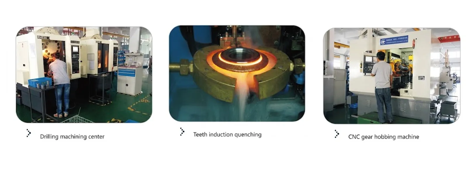
Normas GB/T — Normas Nacionais Chinesas para Polias Síncronas
As normas nacionais chinesas, sob a estrutura GB/T, definem a geometria dos dentes e os requisitos de material para polias síncronas fabricadas e vendidas no mercado interno chinês. Como fornecedor de polias sincronizadoras na China, produzimos a série L. polia de sincronização de furo reto Em nossos produtos, o processo de fabricação segue as normas GB/T aplicáveis para seleção da qualidade do material, tratamento térmico e inspeção de tolerância dimensional, garantindo que os produtos atendam aos requisitos de qualidade dos mercados nacional e internacional, sem a necessidade de sistemas de produção paralelos para diferentes destinos.
Normas ICONTEC e NTC — Colômbia e América Latina
Na Colômbia e em outros países membros da Comunidade Andina, os componentes de transmissão de potência utilizados em máquinas industriais devem estar em conformidade com as normas ICONTEC NTC aplicáveis, que estão alinhadas com as referências ISO e ANSI para sistemas de transmissão por correia. Compradores na Colômbia, Peru, Chile e Brasil que utilizam o modelo L100 polia de sincronização de furo reto As unidades de automação e processamento fabricadas localmente devem verificar se o padrão dimensional do componente (ANSI/RMA ou ISO) é reconhecido pela documentação de projeto do fabricante original da máquina para garantir a compatibilidade.
FDA 21 CFR Parte 820 — Fabricação de Dispositivos Médicos (EUA)
Para polias de correia de distribuição personalizadas usados em equipamentos de fabricação de dispositivos médicos regulamentados pela FDA — incluindo o polia de sincronização de furo reto Em configurações de furos personalizados, o fornecedor deve ser capaz de fornecer documentação de rastreabilidade do material, registros de inspeção dimensional e evidências de controle de processo consistentes com os requisitos de qualificação de fornecedores do fabricante do dispositivo, conforme a norma 21 CFR Parte 820. Os compradores que especificarem unidades de polias de sincronização de furo reto em aço L100 para acionamentos de equipamentos de laboratório médico ou de diagnóstico devem esclarecer os requisitos de documentação no momento da consulta para evitar atrasos no fornecimento durante a qualificação do equipamento do fabricante original (OEM).
7. Produtos relacionados
UM polia de sincronização de furo reto atua como parte de um conjunto completo sistema de transmissão por correia sincronizadaOs seguintes produtos complementares garantem total compatibilidade do sistema e oferecem suporte à aquisição centralizada para engenheiros e compradores que especificam conjuntos completos de acionamento por correia de distribuição juntamente com o polia de sincronização de furo reto.
Barras dentadas padrão com passo métrico
As barras dentadas padrão com passo métrico são o complemento de movimento linear para as polias de sincronização rotativas de furo reto. Quando usadas em conjunto com o L100 polia de sincronização de furo reto Com uma correia dentada compatível, as barras dentadas criam acionamentos de posicionamento linear que oferecem a mesma sincronização sem deslizamento que os acionamentos por correia dentada rotativa — essenciais para acionamentos de eixos CNC, indexação de esteiras transportadoras e sistemas de posicionamento de robôs lineares. Nossa série de barras dentadas abrange todos os principais passos métricos e em polegadas, incluindo o perfil de passo L, para compatibilidade direta com as polias da série L100 e correias padrão da série L.
Polia em V

Nosso Polia em V A gama de produtos foi concebida para utilização em conjunto com polias de distribuição de furo reto em máquinas que combinam secções de transmissão por correia síncrona e não síncrona. As polias de correia em V são frequentemente utilizadas nos estágios de entrada do motor, onde a tolerância ao deslizamento é aceitável, com a polia de distribuição de furo reto a lidar com o posicionamento de precisão a jusante. (A frase seguinte parece estar incompleta e sem contexto suficiente para tradução precisa.) polia de sincronização de furo reto A utilização de unidades e polias em V de um único fornecedor garante padrões consistentes de qualidade de fabricação, logística simplificada e um único contato técnico para suporte ao projeto do sistema de acionamento, reduzindo a complexidade de aquisição para equipes de engenharia globais.
8. Sobre nós
Somos um fabricante especializado em polias sincronizadoras de furo reto de precisão e componentes de transmissão por correia sincronizada, fornecendo para os setores de automação, embalagem, processamento de alimentos, transporte, impressão e equipamentos médicos em todo o mundo. Nossa série L polia de sincronização de furo reto Nossa linha de polias sincronizadoras é fabricada sob processos de gestão de qualidade certificados pela ISO 9001, com geometria dos dentes em conformidade com as tolerâncias ANSI/RMA IP-24 e ISO 5295. Como um fabricante consolidado de polias sincronizadoras na China, atendemos fabricantes de máquinas OEM, integradores de sistemas e distribuidores de MRO na América do Norte, Europa, Sudeste Asiático, Austrália e América Latina. polias de correia de distribuição personalizadas A capacidade amplia o padrão L100 polia de sincronização de furo reto Oferecemos uma gama de opções, desde diâmetros de furo não padronizados, comprimentos de cubo modificados e tratamentos especiais de proteção contra corrosão, atendendo às necessidades de compradores que não podem utilizar o furo pré-usinado padrão em suas especificações de eixo de máquina.
Oficina


Perguntas frequentes
Perguntas frequentes de engenheiros, gerentes de compras e distribuidores do mundo todo sobre o L100 polia de sincronização de furo reto e sistemas de transmissão por correia de distribuição relacionados.
Q1. O que é uma polia de distribuição com furo reto e como ela difere de uma polia com bucha cônica ou de engate rápido em uma aplicação de transmissão industrial?
Q2. Onde posso encontrar um fornecedor confiável de polias de distribuição de furo reto L100 em estoque para envio na mesma semana para a América do Norte ou Europa?
Q3. Como calculo o número correto de dentes de uma polia sincronizadora L100 para atingir uma relação de velocidade específica no meu sistema de acionamento de esteira transportadora na Austrália?
Q4. Qual a diferença entre as polias da correia de distribuição da série L e da HTD, e qual devo escolher para acionar uma máquina de roteamento CNC?
Q5. Qual correia de distribuição devo usar com a polia de distribuição de furo reto 25 L 100 e qual a largura da correia indicada pelo código 100?
Q6. As polias de sincronização L100 em ferro fundido estão disponíveis com furo acabado e parafuso de fixação, prontas para instalação imediata em uma fábrica de processamento de alimentos no Sudeste Asiático?
Q7. Qual é a diferença entre os códigos de flange 6F, 6WF, 6W e 6A na série de polias de distribuição de furo reto L100?
Editor: PXY
Produtos relacionados
-
Polia de sincronização EP-H75 de 12,7 mm com furo reto em aço e ferro fundido
-
Polia de sincronização EP-H150 de 12,7 mm com furo reto em aço e ferro fundido
-

Polia de sincronização EP-H200 de 12,7 mm com furo reto em aço e ferro fundido
-
Polia de sincronização EP-MXL de alumínio com furo reto de 2,032 mm