
Descrizione del prodotto
CHINAMFG Machinery offers a wide range of high quality Timing Belt Pulleys and Toothed Bars / Timing Bars. Standard and non-standard pulleys according to drawings are available.
Types of material:
1. AlCuMgPb 6061 6082 Aluminum Timing Pulley
2. C45E 1045 S45C Carbon Steel Timing Pulley
3. GG25 HT250 Cast Iron Timing Pulley
4. SUS303 SUS304 AISI431 Stainless Steel Timing Pulley
5. Other material on demand, such as cooper, bronze and plastic
Types of surface treatment
1. Anodized surface -Aluminum Pulleys
2. Hard anodized surface — Aluminum Pulleys
3. Black Oxidized surface — Steel Pulleys
4. Zinc plated surface — Steel Pulleys
5. Chromate surface — Steel Pulleys; Cast Iron Pulleys
6. Nickel plated surface –Steel Pulleys; Cast Iron Pulleys
Types of teeth profile
| Teeth Profile | Pitch |
| HTD | 3M,5M,8M,14M,20M |
| AT | AT5,AT10,AT20 |
| T | T2.5,T5,T10 |
| MXL | 0.08″(2.032MM) |
| XL | 1/5″(5.08MM) |
| L | 3/8″(9.525MM) |
| H | 1/2″(12.7MM) |
| XH | 7/8″(22.225MM) |
| XXH | 1 1/4″(31.75MM) |
| STS STPD | S2M,S3M,S4.5M,S5M,S8M,S14M |
| RPP | RPP5M,RPP8M,RPP14M,RPP20M |
| PGGT | PGGT 2GT, 3GT and 5GT |
| PCGT | GT8M,GT14M |
Types of pitches and sizes
Imperial Inch Timing Belt Pulley,
1. Pilot Bore MXL571 for 6.35mm timing belt; teeth number from 16 to 72;
2. Pilot Bore XL037 for 9.53mm timing belt; teeth number from 10 to 72;
3. Pilot Bore, Taper Bore L050 for 12.7mm timing belt; teeth number from 10 to 120;
4. Pilot Bore, Taper Bore L075 for 19.05mm timing belt; teeth number from 10 to 120;
5. Pilot Bore, Taper Bore L100 for 25.4mm timing belt; teeth number from 10 to 120;
6. Pilot Bore, Taper Bore H075 for 19.05mm timing belt; teeth number from 14 to 50;
7. Pilot Bore, Taper Bore H100 for 25.4mm timing belt; teeth number from 14 to 156;
8. Pilot Bore, Taper Bore H150 for 38.1mm timing belt; teeth number from 14 to 156;
9. Pilot Bore, Taper Bore H200 for 50.8mm timing belt; teeth number from 14 to 156;
10. Pilot Bore, Taper Bore H300 for 76.2mm timing belt; teeth number from 14 to 156;
11. Taper Bore XH200 for 50.8mm timing belt; teeth number from 18 to 120;
12. Taper Bore XH300 for 76.2mm timing belt; teeth number from 18 to 120;
13. Taper Bore XH400 for 101.6mm timing belt; teeth number from 18 to 120;
Metric Timing Belt Pulley T and AT
1. Pilot Bore T2.5-16 for 6mm timing belt; teeth number from 12 to 60;
2. Pilot Bore T5-21 for 10mm timing belt; teeth number from 10 to 60;
3. Pilot Bore T5-27 for 16mm timing belt; teeth number from 10 to 60;
4. Pilot Bore T5-36 for 25mm timing belt; teeth number from 10 to 60;
5. Pilot Bore T10-31 for 16mm timing belt; teeth number from 12 to 60;
6. Pilot Bore T10-40 for 25mm timing belt; teeth number from 12 to 60;
7. Pilot Bore T10-47 for 32mm timing belt; teeth number from 18 to 60;
8. Pilot Bore T10-66 for 50mm timing belt; teeth number from 18 to 60;
9. Pilot Bore AT5-21 for 10mm timing belt; teeth number from 12 to 60;
10. Pilot Bore AT5-27 for 16mm timing belt; teeth number from 12 to 60;
11. Pilot Bore AT5-36 for 25mm timing belt; teeth number from 12 to 60;
12. Pilot Bore AT10-31 for 16mm timing belt; teeth number from 15 to 60;
13. Pilot Bore AT10-40 for 25mm timing belt; teeth number from 15 to 60;
14. Pilot Bore AT10-47 for 32mm timing belt; teeth number from 18 to 60;
15. Pilot Bore AT10-66 for 50mm timing belt; teeth number from 18 to 60;
Metric Timing Belt Pulley HTD3M, 5M, 8M, 14M
1. HTD3M-06; 3M-09; 3M-15; teeth number from 10 to 72;
2. HTD5M-09; 5M-15; 5M-25; teeth number from 12 to 72;
3. HTD8M-20; 8M-30; 8M-50; 8M-85 teeth number from 22 to 192;
4. HTD14M-40; 14M-55; 14M-85; 14M-115; 14M-170; teeth number from 28-216;
5. Taper Bore HTD5M-15; 8M-20; 8M-30; 8M-50; 8M-85; 14M-40; 14M-55; 14M-85;
14M-115; 14M-170
Metric Timing Belt Pulleys for Poly Chain GT2 Belts
1. PCGT8M-12; PCGT8M-21; PCGT8M-36; PCGT8M-62;
2. PCGT14M-20; PCGT14M-37; PCGT14M-68; PCGT14M-90; PCGT14M-125;
Power Grip CHINAMFG Tooth/ PGGT 2GT, 3GT and 5GT
1. 2GT-06, 2GT-09 for timing belt width 6mm and 9mm
2. 3GT-09, 3GT-15 for timing belt width 9mm and 15mm
3. 5GT-15, 5GT-25 for timing belt width 15mm and 25mm
OMEGA RPP HTD Timing Pulleys
1. RPP3M-06; 3M-09; 3M-15; teeth number from 10 to 72;
2. RPP5M-09; 5M-15; 5M-25; teeth number from 12 to 72;
3. RPP8M-20; 8M-30; 8M-50; 8M-85 teeth number from 22 to 192;
4. RPP14M-40; 14M-55; 14M-85; 14M-115; 14M-170; teeth number from 28-216;
5. Taper Bore RPP5M-15; 8M-20; 8M-30; 8M-50; 8M-85; 14M-40; 14M-55; 14M-85;
14M-115; 14M-170 /* March 10, 2571 17:59:20 */!function(){function s(e,r){var a,o={};try{e&&e.split(“,”).forEach(function(e,t){e&&(a=e.match(/(.*?):(.*)$/))&&1
| Certification: | ISO |
|---|---|
| Pulley Sizes: | Timing |
| Processo di produzione: | Sawing |
| Personalizzazione: | Disponibile | Richiesta personalizzata |
|---|
.shipping-cost-tm .tm-status-off{background: none;padding:0;color: #1470cc}
| Shipping Cost: Estimated freight per unit. | about shipping cost and estimated delivery time. |
|---|
| Payment Method: |
|
|---|---|
| Initial Payment Full Payment |
| Currency: | US$ |
|---|
| Return&refunds: | You can apply for a refund up to 30 days after receipt of the products. |
|---|
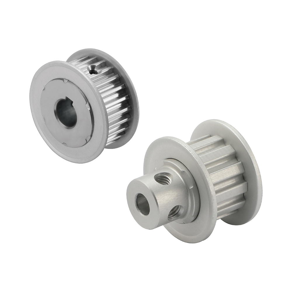
How do timing pulleys contribute to efficient power distribution?
Timing pulleys play a crucial role in ensuring efficient power distribution in various mechanical systems. Here’s how timing pulleys contribute to efficient power distribution:
1. Precise Timing and Synchronization:
Timing pulleys, in conjunction with timing belts or chains, synchronize the rotation of different components within a system. By maintaining precise timing between the input and output shafts, timing pulleys ensure that power is distributed accurately and efficiently. This synchronization prevents power loss due to misalignment or timing discrepancies.
2. Positive Drive System:
Timing pulleys create a positive drive system when paired with timing belts or chains. The teeth on the pulleys interlock with the teeth on the belt or chain, creating a firm grip that eliminates slippage. This positive drive ensures that power is efficiently transmitted from the driving pulley to the driven pulley without any energy loss.
3. Load Distribution:
Timing pulleys help distribute the load evenly across the system by transmitting power from the driving pulley to the driven pulley. The pulley’s design and tooth profile enable the load to be distributed over a larger contact area, reducing stress concentration on individual components. This even load distribution enhances the overall efficiency of power transmission.
4. Reduced Friction and Wear:
Timing pulleys, particularly those made of materials with low friction coefficients, minimize friction and wear during power transmission. The smooth engagement between the pulley teeth and the belt or chain reduces energy losses caused by friction. Additionally, materials with excellent wear resistance properties extend the lifespan of the pulleys, ensuring long-term efficiency.
5. Controllo della tensione:
Timing pulleys, in combination with tensioner and idler pulleys, help maintain the appropriate tension in the timing belt or chain. Proper tension control ensures that the belt or chain remains securely engaged with the pulleys, preventing power loss due to slippage. By maintaining optimal tension, timing pulleys contribute to efficient power distribution throughout the system.
6. System Optimization:
Timing pulleys allow for system optimization by providing flexibility in gear ratios and power transmission configurations. By selecting pulleys with different diameters or tooth profiles, engineers can adjust the speed and torque distribution within the system. This optimization ensures that power is distributed efficiently, matching the requirements of the specific application.
Overall, timing pulleys ensure efficient power distribution by providing precise timing, creating a positive drive system, evenly distributing loads, reducing friction and wear, controlling tension, and enabling system optimization. These factors contribute to the overall efficiency, reliability, and performance of mechanical systems where timing pulleys are utilized.
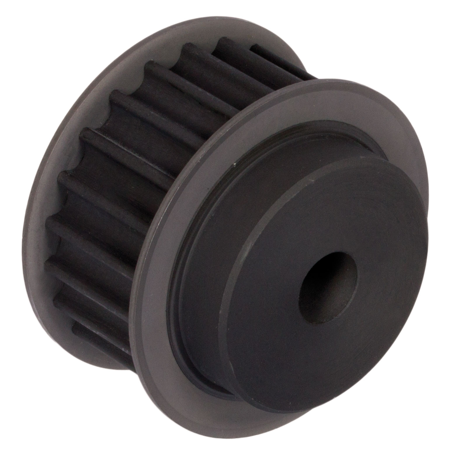
How do timing pulleys impact the performance of 3D printers?
Timing pulleys play a significant role in determining the performance and accuracy of 3D printers. Here’s an explanation of how timing pulleys impact the performance of 3D printers:
1. Motion Control:
Timing pulleys, in conjunction with belts or chains, are used to control the movement of the print head and build platform in 3D printers. The motor drives the driving pulley, which is connected to the print head or build platform through a timing belt or chain. The driven pulley on the print head or build platform receives the rotational motion from the driving pulley, resulting in precise and synchronized movement. The accuracy and quality of the printed object depend on the precise control and synchronization facilitated by the timing pulleys.
2. Positioning Accuracy:
Timing pulleys contribute to the positioning accuracy of 3D printers. The teeth on the timing belt or chain mesh with the teeth on the pulleys, creating positive engagement. This ensures that the print head or build platform moves precisely according to the instructions from the control system. The accuracy of the timing pulley system directly affects the dimensional accuracy and surface finish of the printed object.
3. Speed and Acceleration:
Timing pulleys allow for control of the speed and acceleration of the print head and build platform in 3D printers. By varying the diameter or the number of teeth on the pulleys, different gear ratios can be achieved. This enables printers to control the speed and acceleration of the print head or build platform, affecting printing time, print quality, and the ability to handle intricate details and complex geometries.
4. Print Resolution:
The resolution of a 3D printer refers to the smallest feature size that can be accurately reproduced. Timing pulleys play a role in determining the achievable print resolution. The finer the pitch and the more teeth per unit length on the timing belt or chain, the higher the resolution that can be achieved. Timing pulleys with smaller teeth allow for finer positioning and more precise movement, enabling the printer to produce objects with intricate details and smooth surfaces.
5. Noise and Vibration:
Properly designed and maintained timing pulley systems contribute to reducing noise and vibration in 3D printers. Well-aligned and tensioned timing belts or chains, along with accurately machined pulleys, minimize backlash and ensure smooth and quiet operation. This is particularly important during rapid movements and changes in direction, as excessive noise and vibration can affect print quality and overall printer performance.
6. Maintenance and Durability:
The durability and maintenance requirements of the timing pulley system impact the overall performance of 3D printers. High-quality timing pulleys and belts or chains are essential to ensure longevity and reliable operation. Regular inspection, tensioning, and replacement of worn or damaged components are necessary to maintain optimal performance and prevent print quality issues caused by a degraded timing pulley system.
7. Extruder and Filament Control:
In addition to controlling the movement of the print head and build platform, timing pulleys may also be used in the extruder assembly of 3D printers. Timing pulleys help drive the filament feeding mechanism, ensuring consistent and controlled extrusion of the filament during the printing process. The accurate and synchronized movement facilitated by the timing pulleys contributes to maintaining filament tension and preventing issues such as under-extrusion or filament jams.
By understanding the impact of timing pulleys on 3D printer performance, manufacturers and users can optimize the design, calibration, and maintenance of the timing pulley systems to achieve accurate, reliable, and high-quality 3D prints.
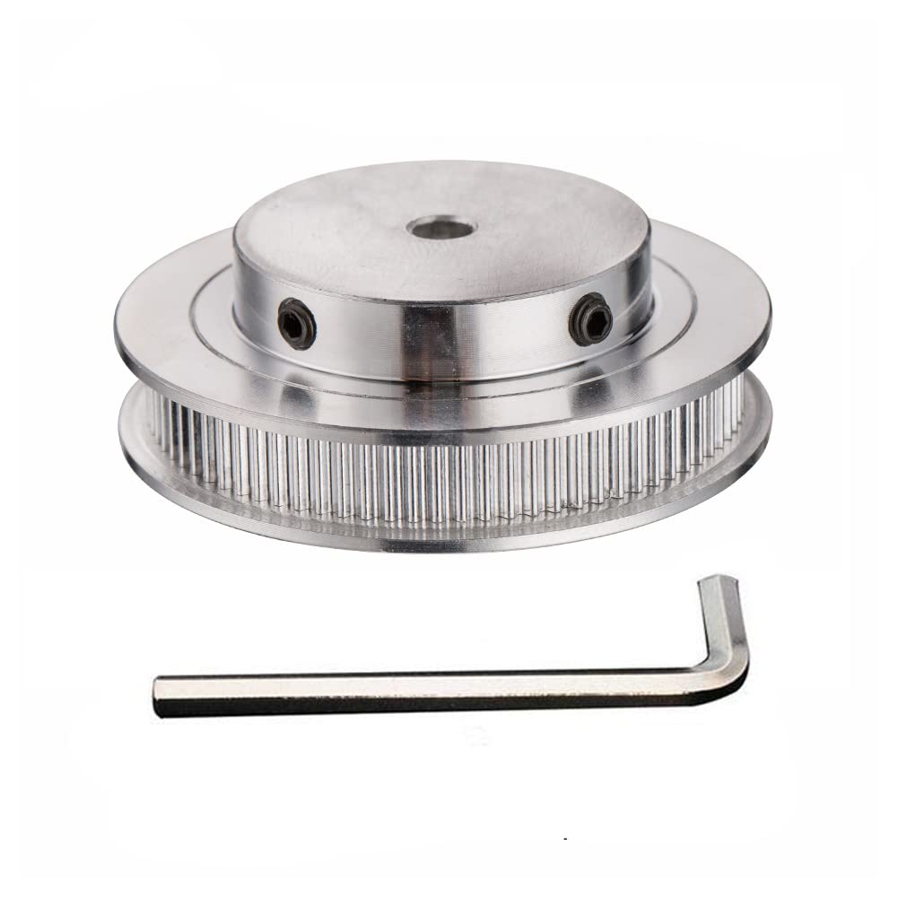
In che cosa si differenzia una puleggia di distribuzione da una puleggia standard?
Una puleggia dentata si differenzia da una puleggia standard per design e funzionalità. Sebbene entrambi i tipi di puleggia siano utilizzati nei sistemi meccanici, svolgono funzioni diverse e presentano caratteristiche distinte. Ecco una spiegazione delle principali differenze tra una puleggia dentata e una puleggia standard:
1. Profilo dentellato:
La differenza più significativa tra una puleggia dentata e una puleggia standard risiede nella presenza di denti sulla prima. Le pulegge dentate presentano scanalature o denti sulla loro superficie circonferenziale che si innestano con i denti corrispondenti delle cinghie di distribuzione. Questo profilo dentato consente un innesto preciso tra la puleggia e la cinghia, garantendo un movimento accurato e prevenendo lo slittamento. Al contrario, le pulegge standard presentano in genere una scanalatura liscia o a V che permette l'utilizzo di cinghie piatte o trapezoidali, la cui trasmissione di potenza si basa sull'attrito.
2. Sincronizzazione e temporizzazione:
Le pulegge dentate sono progettate specificamente per applicazioni che richiedono una fasatura e una sincronizzazione precise. I denti della puleggia dentata si ingranano con i denti della cinghia di distribuzione, creando un sistema di trasmissione efficace. Ciò garantisce che il movimento rotatorio della puleggia motrice venga trasferito con precisione alle pulegge condotte, mantenendo la sincronizzazione e una fasatura accurata. Le pulegge standard, al contrario, non offrono questo livello di precisione nella fasatura e sono comunemente utilizzate in applicazioni in cui la sincronizzazione non è critica.
3. Trasmissione di potenza:
Una puleggia dentata viene utilizzata principalmente per la trasmissione di potenza in applicazioni che richiedono un controllo preciso del movimento. L'innesto preciso tra i denti della puleggia dentata e la cinghia di distribuzione garantisce un trasferimento di potenza efficiente senza slittamenti. Ciò è particolarmente importante in applicazioni in cui sono necessari rapporti di velocità e trasmissione di coppia accurati. Le pulegge standard, pur essendo anch'esse utilizzate per la trasmissione di potenza, si basano sull'attrito tra la puleggia e la cinghia per il trasferimento di potenza, il che può causare slittamenti sotto carichi pesanti o ad alte velocità.
4. Personalizzazione e configurazioni:
Le pulegge dentate offrono un'ampia gamma di opzioni di personalizzazione per soddisfare i requisiti specifici di ogni applicazione. Possono essere realizzate con diversi profili dei denti, passi e numero di denti per ottenere i rapporti di velocità e la trasmissione di coppia desiderati. Le pulegge standard, al contrario, offrono meno opzioni di personalizzazione e sono generalmente disponibili in dimensioni e configurazioni standard.
5. Manutenzione e affidabilità:
Le pulegge e le cinghie di distribuzione richiedono meno manutenzione rispetto alle pulegge e alle cinghie standard. Il profilo dentato delle pulegge di distribuzione impedisce lo slittamento, riducendo la necessità di frequenti regolazioni della tensione. Inoltre, l'innesto preciso tra la puleggia e la cinghia di distribuzione garantisce una trasmissione di potenza affidabile con minima usura e allungamento della cinghia.
Nel complesso, le principali differenze tra una puleggia dentata e una puleggia standard risiedono nel profilo dentato, nelle capacità di sincronizzazione, nella precisione della fasatura, nelle opzioni di personalizzazione e nei requisiti di manutenzione. Le pulegge dentate sono progettate specificamente per applicazioni che richiedono un controllo del movimento e una sincronizzazione accurati, mentre le pulegge standard sono più comunemente utilizzate dove la precisione della fasatura non è fondamentale.


editor di CX
2024-01-25