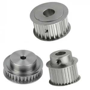

พูลเลย์ไทม์มิ่งแบบรูตรง EP-L50 ขนาด 9.525 มม.
พูลเลย์ไทม์มิ่งแบบรูตรง รุ่น EP-L050 ระยะห่างฟัน 9.525 มม. — ผลิตจากเหล็กและเหล็กหล่อ ได้รับการออกแบบทางวิศวกรรมอย่างแม่นยำสำหรับระบบขับเคลื่อนแบบซิงโครนัสที่มีระยะห่างฟัน 9.525 มม. มีให้เลือกจำนวนฟันตั้งแต่ 10 ถึง 120 ซี่ พูลเลย์เหล่านี้ให้ตัวเลือกอัตราส่วนความเร็วที่หลากหลายสำหรับการใช้งานในอุตสาหกรรมต่างๆ ผลิตจากเหล็กคุณภาพสูง (ชนิด 6F/6WF) หรือเหล็กหล่อ (ชนิด 6W/6A) จึงมั่นใจได้ถึงความทนทานและประสิทธิภาพที่เชื่อถือได้ภายใต้ภาระที่แตกต่างกัน
ขนาดที่สำคัญ ได้แก่ ความกว้างของหน้าแปลน (F) ที่สม่ำเสมอ 19 มม. ในทุกรุ่น รอกขนาดเล็ก (10-36 ฟัน) มีความยาว (L) 28-32 มม. ในขณะที่รุ่นขนาดใหญ่ (40-120 ฟัน) จะยาวถึง 32-42 มม. ซีรีส์นี้รองรับขนาดรู (Dm) ที่หลากหลาย ตั้งแต่ 20 มม. สำหรับรอก 10 ฟันขนาดเล็กที่สุด ไปจนถึง 75 มม. สำหรับรุ่น 65-120 ฟันขนาดใหญ่ที่สุด ด้วยเส้นผ่านศูนย์กลางภายนอก (De) ที่แม่นยำ ตั้งแต่ 29.56 มม. ถึง 363.07 มม. รอกเหล่านี้จึงให้การส่งกำลังที่แม่นยำสำหรับระบบอัตโนมัติ หุ่นยนต์ และเครื่องจักรหนัก
พูลเลย์ไทม์มิ่งแบบรูตรงใกล้เคียง | พูลเลย์ไทม์มิ่ง | ซีรี่ส์ L
EP-L050 9.525 มม.
พูลเลย์ไทม์มิ่งแบบรูตรง
ระยะห่างระหว่างฟัน (L pitch) 9.525 มม. • 10 ถึง 120 ฟัน • เหล็กกล้า (6F / 6WF) และเหล็กหล่อ (6W / 6A) • รูปแบบ 6F / 6WF / 6W / 6A • เส้นผ่านศูนย์กลางระยะห่างระหว่างฟัน 30.32 มม. ถึง 363.83 มม. • ได้รับการรับรองมาตรฐาน ISO 9001:2015 • พูลเลย์ไทม์มิ่งจากจีน จัดจำหน่ายแบบ OEM ทั่วโลก
1. ข้อมูลจำเพาะทางเทคนิค — พูลเลย์ไทม์มิ่งแบบรูตรง EP-L050
ซีรี่ส์ L050 • ระยะห่างฟัน 9.525 มม. • รูตรง • วัสดุ: เหล็ก (6F/6WF, 10–48 ฟัน) และเหล็กหล่อ (6W/6A, 49–120 ฟัน)
ขนาดทั้งหมดระบุเป็นมิลลิเมตร Dp = เส้นผ่านศูนย์กลางเกลียว, De = เส้นผ่านศูนย์กลางภายนอก, Df = เส้นผ่านศูนย์กลางภายนอกของหน้าแปลน (ถ้ามี), Dm = เส้นผ่านศูนย์กลางภายนอกของดุม, Di = รูเจาะ, F = ความหนาของหน้าแปลน, L = ความยาวของดุม, d = ความลึกของร่องลิ่ม หมายเลขหน้าแปลนแสดงถึงรหัสมาตรฐานของแผ่นหน้าแปลน
| รหัสชิ้นส่วน | ฟัน | พิมพ์ | วัสดุ | ดป (มม.) | เดอ (มม.) | ดฟ (มม.) | ดม (มม.) | เส้นผ่านศูนย์กลาง (มม.) | เอฟ (มม.) | L (มม.) | d (มม.) | หมายเลขหน้าแปลน |
|---|---|---|---|---|---|---|---|---|---|---|---|---|
| 10 ลิตร 050 | 10 | 6F | เหล็ก | 30.32 | 29.56 | 37 | 20 | – | 19 | 28 | 8 | 50 |
| 11 ลิตร 050 | 11 | 6F | 33.35 | 32.59 | 37 | 22 | – | 19 | 30 | 8 | 50 | |
| 12 ลิตร 050 | 12 | 6F | 36.38 | 35.62 | 43 | 24 | – | 19 | 30 | 8 | 52 | |
| 13 ลิตร 050 | 13 | 6F | 39.41 | 38.65 | 44 | 28 | – | 19 | 30 | 8 | 83 | |
| 14 ลิตร 050 | 14 | 6F | 42.45 | 41.68 | 48 | 28 | – | 19 | 30 | 8 | 54 | |
| 15 ลิตร 050 | 15 | 6F | 45.48 | 44.72 | 51 | 34 | – | 19 | 30 | 8 | 55 | |
| 16 ลิตร 050 | 16 | 6F | 48.51 | 47.75 | 54 | 36 | – | 19 | 32 | 8 | 56 | |
| 17 ลิตร 050 | 17 | 6F | 51.54 | 50.78 | 57 | 36 | – | 19 | 32 | 10 | 57 | |
| 18 ลิตร 050 | 18 | 6F | 54.57 | 53.81 | 60 | 40 | – | 19 | 32 | 10 | 58 | |
| 19 ลิตร 050 | 19 | 6F | 57.61 | 56.84 | 64 | 40 | – | 19 | 32 | 10 | 59 | |
| 20 ลิตร 050 | 20 | 6F | 60.64 | 59.88 | 66.5 | 40 | – | 19 | 32 | 10 | 60 | |
| 21 ลิตร 050 | 21 | 6F | 63.67 | 62.91 | 70 | 45 | – | 19 | 32 | 10 | 61 | |
| 22 ลิตร 050 | 22 | 6F | 66.70 | 65.94 | 75 | 45 | – | 19 | 32 | 10 | 62 | |
| 23 ลิตร 050 | 23 | 6F | 69.73 | 68.97 | 79 | 55 | – | 19 | 32 | 10 | 63 | |
| 24 ลิตร 050 | 24 | 6F | 72.77 | 72.00 | 79 | 55 | – | 19 | 32 | 10 | 63 | |
| 25 ลิตร 050 | 25 | 6F | 75.80 | 75.04 | 82.5 | 58 | – | 19 | 32 | 10 | 64 | |
| 26 ลิตร 050 | 26 | 6F | 78.83 | 78.07 | 86 | 58 | – | 19 | 32 | 11 | 65 | |
| 27 ลิตร 050 | 27 | 6F | 81.86 | 81.10 | 86 | 58 | – | 19 | 32 | 11 | 65 | |
| 28 ลิตร 050 | 28 | 6F | 84.89 | 84.13 | 91 | 58 | – | 19 | 32 | 11 | 66 | |
| 29 ลิตร 050 | 29 | 6F | 87.93 | 87.16 | 94 | 58 | – | 19 | 32 | 11 | 67 | |
| 30 ลิตร 050 | 30 | 6F | 90.96 | 90.20 | 97 | 70 | – | 19 | 32 | 11 | 68 | |
| 32 ลิตร 050 | 32 | 6F | 97.02 | 96.26 | 102 | 70 | – | 19 | 32 | 11 | 70 | |
| 33 ลิตร 050 | 33 | 6F | 100.05 | 99.29 | 106 | 70 | – | 19 | 32 | 11 | 71 | |
| 34 ลิตร 050 | 34 | 6F | 103.08 | 102.32 | 112 | 70 | – | 19 | 32 | 11 | 72 | |
| 35 ลิตร 050 | 35 | 6F | 106.12 | 105.35 | 112 | 70 | – | 19 | 32 | 11 | 72 | |
| 36 ลิตร 050 | 36 | 6F | 109.15 | 108.39 | 115 | 70 | – | 19 | 32 | 11 | 74 | |
| 40 ลิตร 050 | 40 | 6WF | 121.28 | 120.51 | 128 | 70 | 100 | 19 | 32 | 11 | 78 | |
| 41 ลิตร 050 | 41 | 6WF | 124.31 | 123.55 | 135 | 70 | 103 | 19 | 32 | 11 | 80 | |
| 42 ลิตร 050 | 42 | 6WF | 127.34 | 126.58 | 135 | 70 | 106 | 19 | 32 | 11 | 80 | |
| 44 ลิตร 050 | 44 | 6WF | 133.40 | 132.64 | 142 | 70 | 112 | 19 | 32 | 11 | 81 | |
| 45 ลิตร 050 | 45 | 6WF | 136.44 | 135.67 | 142 | 70 | 115 | 19 | 32 | 11 | 81 | |
| 47 ลิตร 050 | 47 | 6WF | 142.50 | 141.74 | 150 | 70 | 121 | 19 | 32 | 11 | 85 | |
| 48 ลิตร 050 | 48 | 6WF | 145.53 | 144.77 | 150 | 70 | 124 | 19 | 32 | 11 | 85 | |
| 49 ลิตร 050 | 49 | 6 วัตต์ | เหล็กหล่อ | 148.56 | 147.80 | – | 70 | 127 | 19 | 32 | 14 | – |
| 50 ลิตร 050 | 50 | 6 วัตต์ | 151.60 | 150.83 | – | 70 | 130 | 19 | 32 | 14 | – | |
| 52 ลิตร 050 | 52 | 6 วัตต์ | 157.66 | 156.90 | – | 70 | 136 | 19 | 32 | 14 | – | |
| 56 ลิตร 050 | 56 | 6 วัตต์ | 169.79 | 169.02 | – | 70 | 149 | 19 | 32 | 14 | – | |
| 57 ลิตร 050 | 57 | 6 วัตต์ | 172.82 | 172.06 | – | 70 | 152 | 19 | 32 | 14 | – | |
| 60 ลิตร 050 | 60 | 6 วัตต์ | 181.91 | 181.15 | – | 75 | 160 | 19 | 42 | 14 | – | |
| 65 ลิตร 050 | 65 | 6A | 197.07 | 196.31 | – | 75 | 176 | 19 | 42 | 14 | – | |
| 66 แอล 050 | 66 | 6A | 200.11 | 199.34 | – | 75 | 179 | 19 | 42 | 14 | – | |
| 72 ลิตร 050 | 72 | 6A | 218.30 | 217.53 | – | 75 | 197 | 19 | 42 | 14 | – | |
| 84 แอล 050 | 84 | 6A | 254.68 | 253.92 | – | 75 | 233 | 19 | 42 | 14 | – | |
| 90 ลิตร 050 | 90 | 6A | 272.87 | 272.11 | – | 75 | 252 | 19 | 42 | 14 | – | |
| 96 ลิตร 050 | 96 | 6A | 291.06 | 290.30 | – | 75 | 269 | 19 | 42 | 14 | – | |
| 120 ลิตร 050 | 120 | 6A | 363.83 | 363.07 | – | 75 | 342 | 19 | 42 | 14 | – |
หมายเหตุ: ค่า Di (รูเจาะ) ที่ระบุไว้ แสดงว่าไม่มีการเจาะรูด้านในมาก่อน – ดุมล้อจะถูกจัดส่งเป็นโลหะตันพร้อมสำหรับการเจาะรูโดยลูกค้าให้ได้ขนาดเส้นผ่านศูนย์กลางเพลาที่ต้องการ ขนาดรูเจาะมาตรฐานมีให้บริการตามคำขอสำหรับขนาดเพลาเฉพาะ ขนาดร่องลิ่มเป็นไปตามมาตรฐานเส้นผ่านศูนย์กลางเพลาที่เกี่ยวข้อง (JIS หรือ ISO)
2. พูลเลย์ตั้งจังหวะแบบรูตรง EP-L050 — ภาพรวมผลิตภัณฑ์
EP-L050 เป็นชิ้นส่วนที่ผลิตด้วยความแม่นยำสูง พูลเลย์ไทม์มิ่งแบบรูตรง ผลิตตามมาตรฐานระยะห่างฟัน L (ขนาดใหญ่) โดยมีระยะห่างฟัน 9.525 มม. (3/8 นิ้ว) สายพานไทม์มิ่งซีรีส์ระยะห่างฟัน L อยู่ในระดับกลางของระบบสายพานระยะห่างฟันนิ้ว — สูงกว่าซีรีส์ XL (เบาพิเศษ) และ MXL (เบาพิเศษขนาดเล็ก) และต่ำกว่าซีรีส์ H (หนัก) — ให้การผสมผสานระหว่างความสามารถในการรับน้ำหนักของฟันและช่วงความเร็วของระบบที่เหมาะสมกับการใช้งานในระบบอัตโนมัติทางอุตสาหกรรมทั่วไป เครื่องจักรบรรจุภัณฑ์ อุปกรณ์สิ่งทอ และระบบขับเคลื่อนสายพานลำเลียง สายพาน EP-L050 มีจำนวนฟันตั้งแต่ 10 ฟัน (ระยะห่างฟัน 30.32 มม.) ถึง 120 ฟัน (ระยะห่างฟัน 363.83 มม.) ช่วยให้นักออกแบบระบบขับเคลื่อนสามารถเลือกช่วงเส้นผ่านศูนย์กลางระยะห่างฟันที่กว้างมากภายในตระกูลระยะห่างฟันสายพานเดียวกันได้
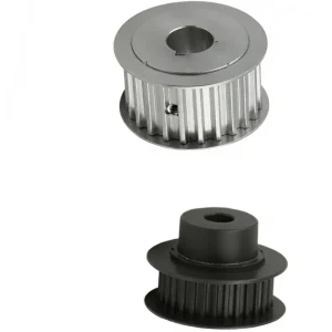
ผลิตภัณฑ์ตระกูล L050 มีให้เลือกสองเกรดวัสดุ ได้แก่ เหล็ก (กำหนดเป็นประเภท 6F และ 6WF ครอบคลุมจำนวนฟันตั้งแต่ 10 ถึง 48 ซี่) และเหล็กหล่อ (กำหนดเป็นประเภท 6W และ 6A ครอบคลุมจำนวนฟันตั้งแต่ 49 ถึง 120 ซี่) การเปลี่ยนวัสดุจากเหล็กในจำนวนฟันน้อยไปเป็นเหล็กหล่อในขนาดเส้นผ่านศูนย์กลางที่ใหญ่ขึ้น สะท้อนให้เห็นถึงความเป็นจริงทางวิศวกรรมที่ว่า พูลเลย์สายพานไทม์มิ่งที่มีเส้นผ่านศูนย์กลางขนาดใหญ่กว่าจะได้ประโยชน์จากมวลของเหล็กหล่อในการลดแรงสั่นสะเทือน ในขณะที่พูลเลย์เหล็กขนาดเล็กกว่าจะได้ประโยชน์จากความแข็งแรงและความสามารถในการขึ้นรูปที่สูงกว่าของเหล็กในขนาดกะทัดรัด พูลเลย์แบบรูตรงทั้งหมดในกลุ่มผลิตภัณฑ์นี้มาพร้อมกับรูเจาะทะลุที่มีความแม่นยำ พร้อมสำหรับการทำร่องลิ่มหรือการติดตั้งสกรูยึดเข้ากับเพลาขับ
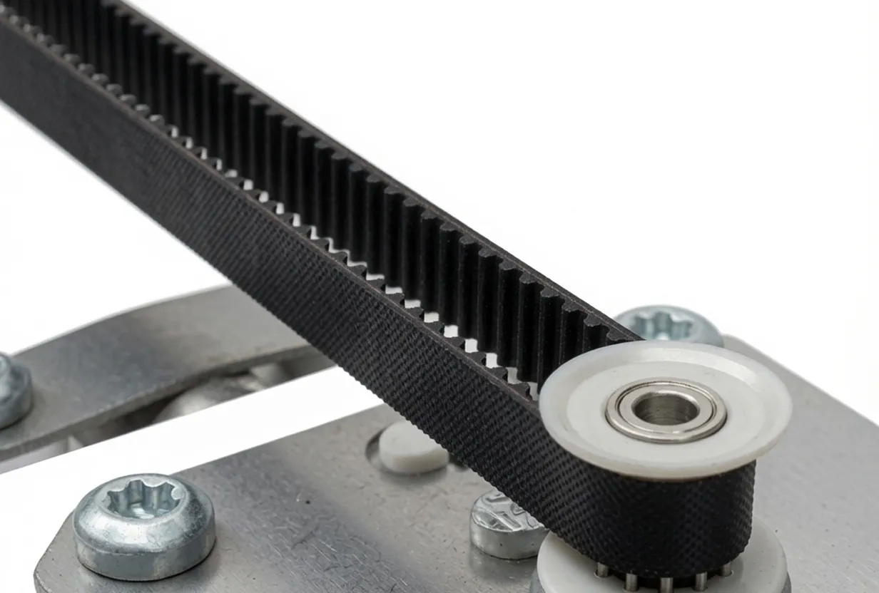
เดอะ พูลเลย์สายพานไทม์มิ่ง ทำหน้าที่เป็นล้อขับหรือล้อตามที่มีฟันเฟือง ซึ่งประกบกับโปรไฟล์ฟันของสายพานไทม์มิ่ง ส่งถ่ายการเคลื่อนที่ในอัตราส่วนคงที่ระหว่างเพลาโดยไม่มีการลื่นไถลหรือการสูญเสียจากการยืดตัวที่เกิดขึ้นในระบบขับเคลื่อนด้วยสายพานหรือโซ่เสียดทาน ในฐานะซัพพลายเออร์รอกไทม์มิ่งจากประเทศจีนที่นำเสนอจำนวนฟันครบทุกช่วง L050 เราจัดจำหน่ายทั้งแบบมาตรฐานและแบบที่ปรับแต่งได้ตามต้องการ ทั้งขนาดรูและหน้ากว้าง ให้แก่ลูกค้า OEM และลูกค้าหลังการขายในอุตสาหกรรมทั่วโลก
3. ข้อได้เปรียบหลัก 5 ประการของผลิตภัณฑ์
กลุ่มผลิตภัณฑ์ EP-L050 ครอบคลุมจำนวนฟันตั้งแต่ 10 ถึง 120 ซี่ในผลิตภัณฑ์ตระกูลเดียวกัน โดยมีเส้นผ่านศูนย์กลางพิทช์ตั้งแต่ 30.32 มม. ถึง 363.83 มม. ความหลากหลายนี้ช่วยให้นักออกแบบระบบขับเคลื่อนสามารถสร้างอัตราส่วนความเร็วที่ต้องการได้เกือบทุกค่าภายในกลุ่มพิทช์สายพาน L โดยไม่ต้องเปลี่ยนไปใช้พิทช์สายพานอื่น ไม่ว่าการใช้งานจะต้องการเฟืองขับขนาดกะทัดรัด 10 ฟันสำหรับเซอร์โวไดรฟ์ความเร็วสูง หรือพูลเลย์ขับขนาดใหญ่ 120 ฟันสำหรับขั้นตอนเอาต์พุตแรงบิดสูงที่ความเร็วต่ำ กลุ่มผลิตภัณฑ์ทั้งหมดมีให้เลือกจากแหล่งเดียวด้วยมาตรฐานวัสดุและขนาดที่สม่ำเสมอ
การเลือกใช้วัสดุเป็นไปตามหลักปฏิบัติที่ดีที่สุดทางวิศวกรรม: เหล็กกล้าสำหรับรอก 10 ถึง 48 ฟัน (แบบ 6F และ 6WF) ซึ่งต้องการความแข็งแรงสูง ความคลาดเคลื่อนในการกลึงที่ละเอียดกว่า และมวลที่ต่ำกว่าในขนาดเส้นผ่านศูนย์กลางที่กะทัดรัด; เหล็กหล่อสำหรับรอก 49 ถึง 120 ฟัน (แบบ 6W และ 6A) ซึ่งขนาดเส้นผ่านศูนย์กลางที่ใหญ่กว่านั้นได้รับประโยชน์จากการลดแรงสั่นสะเทือนและความสามารถในการกลึงของเหล็กหล่อ วัสดุทั้งสองชนิดได้รับการกลึงให้ได้ความแม่นยำของรูปทรงฟันและรูปทรงดุมมาตรฐานเดียวกัน เพื่อให้มั่นใจได้ว่าสายพานจะยึดเกาะได้อย่างถูกต้องตลอดช่วงจำนวนฟันทั้งหมด
ระบบการกำหนดประเภท (6F สำหรับแบบมีขอบแต่ไม่มีแกนกลาง, 6WF สำหรับแบบมีขอบและมีแกนกลาง, 6W สำหรับแบบเปิดและมีแกนกลาง, 6A สำหรับแบบเปิดแต่ไม่มีแกนกลาง สำหรับรอกขนาดใหญ่) ให้ความยืดหยุ่นในการเลือกใช้รอกไทม์มิ่งแบบรูตรงที่มีขอบ ซึ่งจำเป็นสำหรับการนำทางสายพานในแนวด้านข้าง หรือแบบขอบเปิด ซึ่งการติดตามสายพานจะถูกจัดการโดยรูปทรงเรขาคณิตของระบบขับเคลื่อน แบบมีขอบ (6F, 6WF) เป็นมาตรฐานสำหรับงานขับเคลื่อนด้วยสายพานไทม์มิ่งส่วนใหญ่ที่การเบี่ยงเบนในแนวแกนของสายพานเป็นสิ่งที่น่ากังวล ส่วนแบบเปิด (6W, 6A) มักใช้เป็นรอกขับขนาดใหญ่ในระบบขับเคลื่อนแบบสองรอก โดยที่รอกขับขนาดเล็กมีขอบ
โปรไฟล์ฟันแบบ L pitch นั้นถูกกลึงให้มีความแม่นยำตามขนาดที่กำหนดโดย ISO 5294 (ระบบขับเคลื่อนสายพานซิงโครนัส — พูลเลย์) และมาตรฐาน RMA (สมาคมผู้ผลิตยาง) ที่เทียบเท่ากันสำหรับพูลเลย์ไทม์มิ่งแบบ L-pitch ขนาดนิ้ว ความแม่นยำของรูปทรงฟัน — ระยะห่างของฟัน ความสูงของโปรไฟล์ และความกว้างของส่วนสัมผัส — จะเป็นตัวกำหนดว่าสายพานไทม์มิ่งจะเข้าที่ในร่องฟันแต่ละร่องอย่างสมบูรณ์โดยไม่มีการติดขัดหรือมีช่องว่างมากเกินไป ซึ่งทั้งสองอย่างนี้จะลดพื้นที่สัมผัสของฟันที่มีประสิทธิภาพและลดความสามารถในการรับแรงบิดในการทำงานที่กำหนดของระบบขับเคลื่อน หน่วย EP-L050 ทุกชิ้นได้รับการตรวจสอบความแม่นยำของโปรไฟล์ฟันด้วย CMM ก่อนจัดส่ง
การออกแบบรูตรงให้รูทะลุเรียบที่ขนาดเส้นผ่านศูนย์กลางรูมาตรฐาน พร้อมสำหรับการเจาะร่องลิ่มตามข้อกำหนดของลูกค้า หรือการติดตั้งด้วยสกรูยึดบนเพลาขับ แตกต่างจากการออกแบบรูแบบเทเปอร์ล็อคหรือแบบ QD ที่ต้องใช้ชุดบูชที่เข้ากัน พูลเลย์ไทม์มิ่งนี้ติดตั้งเข้ากับเพลาโดยตรงด้วยลิ่มและสกรูยึดแบบมาตรฐาน ซึ่งเป็นวิธีการติดตั้งที่ง่ายที่สุดและต้นทุนต่ำที่สุดสำหรับระบบขับเคลื่อนสายพานไทม์มิ่งในเครื่องจักรบรรจุภัณฑ์ ระบบลำเลียง อุปกรณ์สิ่งทอ และการใช้งานระบบอัตโนมัติทางอุตสาหกรรมทั่วไปทั่วโลก
4. หลักการทำงาน — รอกปรับจังหวะแบบ L-Pitch ขับเคลื่อนระบบสายพานได้อย่างไร
เอ พูลเลย์สายพานไทม์มิ่ง ระบบขับเคลื่อนด้วยสายพานไทม์มิ่งช่วยให้การส่งกำลังเป็นไปอย่างซิงโครนัส โดยการขบกันของฟันที่ยกขึ้นของรอกกับร่องฟันที่ตรงกันของสายพานไทม์มิ่ง แตกต่างจากรอกแบบสายพานตัววีหรือสายพานแบนที่ส่งกำลังผ่านแรงเสียดทานระหว่างสายพานและขอบรอก ระบบขับเคลื่อนด้วยสายพานไทม์มิ่งอาศัยการขบกันของฟันอย่างแม่นยำ แต่ละฟันของสายพานจะเข้าที่ในร่องของรอก และแรงตึงในสายพานจะส่งแรงในแนวสัมผัสจากรอกขับไปยังรอกตาม กลไกการขบกันของฟันนี้ช่วยขจัดปัญหาการลื่นไถลได้อย่างสมบูรณ์ ทำให้รักษาอัตราส่วนความเร็วคงที่ระหว่างเพลาขับและเพลาตามตลอดเวลา โดยไม่คำนึงถึงการเปลี่ยนแปลงของภาระหรือความเร็ว
ระยะห่างระหว่างฟันเฟืองของระบบตั้งเวลา — 9.525 มม. สำหรับซีรี่ส์ L — คือระยะห่างระหว่างศูนย์กลางของฟันเฟืองที่อยู่ติดกันทั้งบนสายพานและรอก จำนวนฟันเฟืองบนรอกจะเป็นตัวกำหนดเส้นผ่านศูนย์กลางระยะห่าง (Dp) ซึ่งเป็นเส้นผ่านศูนย์กลางที่เส้นระยะห่าง (จุดศูนย์กลางของระยะห่างระหว่างฟันเฟืองบนสายพานขณะที่สายพานพันรอบรอก) สำหรับรุ่น EP-L050 ความสัมพันธ์ระหว่างเส้นผ่านศูนย์กลางระยะห่างคือ: Dp = (จำนวนฟัน × ระยะห่าง) / π = (N × 9.525) / π สูตรนี้จะให้ค่าที่แสดงในตารางข้อมูลจำเพาะสำหรับจำนวนฟันเฟืองแต่ละแบบ — ตัวอย่างเช่น 10 ฟัน จะได้ Dp = (10 × 9.525) / π = 30.32 มม. ตามที่ระบุในตาราง
เส้นผ่านศูนย์กลางภายนอก (De) ของพูลเลย์ไทม์มิ่งจะมีขนาดเล็กกว่าเส้นผ่านศูนย์กลางพิทช์เล็กน้อยเสมอ เนื่องจากเส้นพิทช์วิ่งผ่านระนาบกลางของความสูงฟันสายพาน ไม่ใช่ที่ปลายฟันพูลเลย์ De = Dp − 2α โดยที่ α คือระยะเดเดนดัม (ระยะห่างจากเส้นพิทช์ถึงโคนฟันพูลเลย์) ความแตกต่างระหว่างเส้นผ่านศูนย์กลางพิทช์และเส้นผ่านศูนย์กลางภายนอกนี้มีความสำคัญต่อการคำนวณทางเรขาคณิตของระบบขับเคลื่อน — ระยะห่างระหว่างศูนย์กลางของพูลเลย์สองตัวคำนวณโดยใช้เส้นผ่านศูนย์กลางพิทช์ ไม่ใช่เส้นผ่านศูนย์กลางภายนอก
ระบบปรับความตึงสายพานไทม์มิ่งสำหรับสายพานแบบ L-pitch จำเป็นต้องรักษาความตึงของสายพานให้ถูกต้อง เพื่อให้แน่ใจว่าฟันทุกซี่ในส่วนโค้งของการสัมผัสยังคงประกบกันอยู่โดยไม่กระโดดข้ามฟันใดๆ ภายใต้สภาวะแรงบิดสูงสุด ส่วนโค้งของการสัมผัสขั้นต่ำกำหนดไว้ที่อย่างน้อยหกฟันประกบกันที่รอกขนาดเล็กกว่า ซึ่งกำหนดอัตราส่วนขั้นต่ำระหว่างรอกทั้งสองในระบบขับเคลื่อน ความลึกของตัวรอกไทม์มิ่ง (ขนาด L ตั้งแต่ 28 ถึง 42 มม. ในช่วง L050) และความกว้างของหน้าสัมผัสต้องตรงกับความกว้างของสายพานที่ใช้ — หน้าสัมผัสของสายพานต้องแคบกว่าหน้าสัมผัสของรอกเพื่อให้มีระยะห่างขอบที่ถูกต้อง
5. วัสดุและการก่อสร้าง
การเลือกวัสดุสำหรับ พูลเลย์ไทม์มิ่ง มีผลโดยตรงต่อความแม่นยำของรูปทรงฟัน อายุการใช้งาน และความเหมาะสมกับสภาพแวดล้อมการใช้งาน กลุ่มผลิตภัณฑ์ EP-L050 ใช้เกรดวัสดุสองเกรดในช่วงจำนวนฟันที่แตกต่างกัน โดยแต่ละเกรดได้รับการคัดเลือกให้ตรงกับข้อกำหนดด้านโครงสร้างและการผลิตของขนาดรอกที่ครอบคลุม
เหล็กกล้าคาร์บอนปานกลาง (S45C หรือเทียบเท่า) เป็นวัสดุที่กำหนดไว้สำหรับพูลเลย์ L050 ที่มีฟัน 10 ถึง 48 ซี่ ซึ่งเป็นช่วงขนาดเส้นผ่านศูนย์กลางฟันที่เล็กกว่า โดยต้องการความแข็งแรงดึงสูงกว่าเพื่อต้านทานแรงดัดที่โคนฟันภายใต้แรงสัมผัสที่เกิดขึ้นระหว่างการทำงานปกติของสายพานไทม์มิ่ง ดุมเหล็กจะถูกกลึงขึ้นรูปและกัดขึ้นรูปตามรูปทรงฟัน จากนั้นจึงทำการกลึงรูและร่องลิ่มให้ได้ค่าความคลาดเคลื่อนที่ต้องการ สำหรับการป้องกันการกัดกร่อนในสภาพแวดล้อมที่ชื้นหรือสัมผัสกับสารเคมี มีตัวเลือกการชุบสังกะสี ชุบนิกเกิล หรือการเคลือบออกไซด์สีดำให้เลือกตามคำขอสำหรับพูลเลย์ไทม์มิ่งเหล็ก L050
เหล็กหล่อสีเทา (เกรด GG20 / HT200) ใช้สำหรับรอก L050 ที่มีฟัน 49 ถึง 120 ซี่ โดยที่เส้นผ่านศูนย์กลางของฟันที่ใหญ่กว่าจะได้รับประโยชน์จากมวลความร้อนและคุณสมบัติการลดแรงสั่นสะเทือนของเหล็กหล่อ มวลที่มากกว่าของรอกเหล็กหล่อขนาดใหญ่จะทำหน้าที่เหมือนล้อช่วยแรงที่ช่วยลดความผันผวนของแรงบิดในระบบขับเคลื่อนด้วยสายพาน ซึ่งมีประโยชน์อย่างยิ่งในงานที่มอเตอร์ขับเคลื่อนสร้างความผันผวนของความเร็ว (เช่นในมอเตอร์ไฟฟ้ากระแสสลับเฟสเดียวที่โหลดเบา) ซึ่งหากไม่มีความผันผวนนี้ จะส่งผ่านความผันผวนของความเร็วไปยังเพลาที่ขับเคลื่อน เหล็กหล่อยังเข้ากันได้โดยตรงกับสารหล่อลื่นที่ใช้ในกล่องเกียร์แบบปิดซึ่งระบบขับเคลื่อนด้วยสายพานไทม์มิ่งถูกรวมเข้ากับสภาพแวดล้อมที่มีการหล่อลื่น
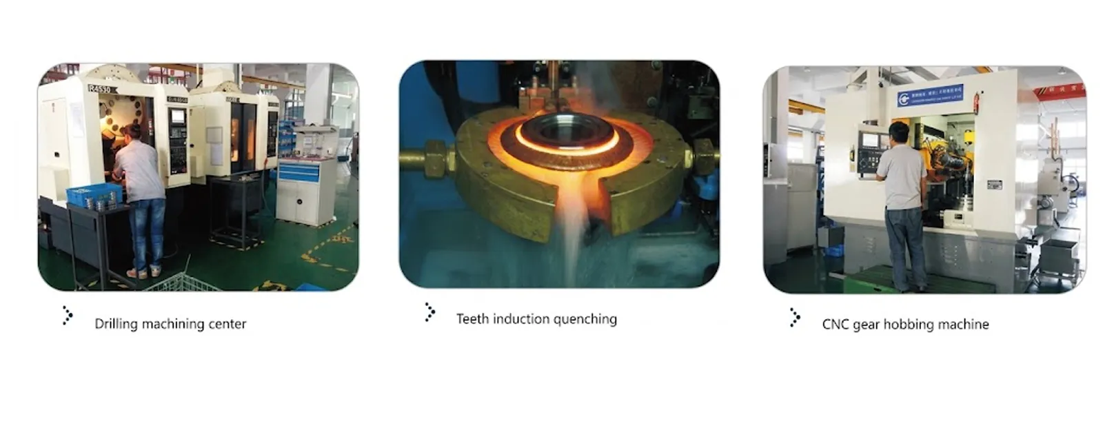
รูปทรงฟันของพูลเลย์ไทม์มิ่ง EP-L050 ทั้งหมดผลิตโดยการกัดขึ้นรูปด้วยเครื่อง CNC โดยใช้ดอกกัดที่ลับคมให้มีรูปทรงฟันแบบ L-pitch กระบวนการกัดขึ้นรูปนี้จะสร้างรูปทรงฟันสี่เหลี่ยมคางหมูตามมาตรฐานซีรี่ส์ L โดยมีค่าความคลาดเคลื่อนของความกว้างของสันฟัน ความลึกของร่อง และมุมด้านข้างที่จำเป็นสำหรับการเข้าคู่ที่ถูกต้องกับสายพานไทม์มิ่งแบบ L-pitch จากผู้ผลิตสายพานมาตรฐานใดๆ การลบคมหลังการกัดขึ้นรูปจะกำจัดขอบคมที่ปลายฟันซึ่งอาจทำให้เกิดการสึกหรอของฟันสายพานเร็วขึ้นเมื่อเข้าและออกจากการเข้าคู่ และพูลเลย์ทั้งหมดจะได้รับการตรวจสอบขนาดตามข้อกำหนดความคลาดเคลื่อนของรูปทรงฟันตามมาตรฐาน ISO 5294 ก่อนจัดส่ง
ขอบของพูลเลย์แบบ Type 6F และ 6WF นั้นเป็นแผ่นเหล็กทรงกลมที่มีหมายเลขขอบเฉพาะ (50 ถึง 85 ในช่วง L050) โดยจะถูกกดหรือขันสกรูติดกับตัวพูลเลย์ เส้นผ่านศูนย์กลางของขอบ Df นั้นใหญ่กว่าเส้นผ่านศูนย์กลางภายนอก De และทำหน้าที่เป็นตัวนำทางด้านข้างสำหรับสายพานไทม์มิ่ง ป้องกันไม่ให้สายพานหลุดออกจากขอบพูลเลย์ภายใต้สภาวะแรงด้านข้าง พูลเลย์เหล็กหล่อแบบ Type 6W และ 6A (49 ฟันขึ้นไป) ไม่มีขอบ เนื่องจากที่เส้นผ่านศูนย์กลางของฟันที่ใหญ่ขึ้น สายพานสามารถถูกนำทางโดยรูปทรงเรขาคณิตของระบบขับเคลื่อนแทนที่จะใช้ขอบของพูลเลย์ ทำให้ลดแรงเฉื่อยในการหมุนของพูลเลย์ขนาดใหญ่ลง

6. การปฏิบัติตามกฎระเบียบ — มาตรฐานสากลสำหรับรอกไทม์มิ่ง
Timing belt pulleys are used globally across industrial, automotive, and consumer machinery applications, and are subject to a range of dimensional and safety standards that ensure interoperability between pulley and belt from different manufacturers. The following standards framework governs the EP-L050 straight bore timing pulley.
ISO 5294 (Synchronous Belt Drives — Pulleys): The primary international standard governing the tooth form, dimensional tolerances, and acceptance criteria for timing belt pulleys in metric and inch pitch series. ISO 5294 specifies the tooth profile geometry, groove width tolerances, and pitch diameter calculation method that ensure interchangeability between pulleys from different manufacturers when used with the same pitch belt. Units in this EP-L050 series are manufactured to conform to the inch-pitch L series tooth dimensions specified in ISO 5294 and the equivalent RMA (Rubber Manufacturers Association) standard IP-22.
EU Machinery Directive 2006/42/EC and EN ISO 4413: When a straight bore timing pulley is incorporated into a machine sold in the European Union, the assembled machine must carry CE marking under the Machinery Directive. The timing belt drive itself (pulley, belt, and guarding) must meet the mechanical safety requirements of EN ISO 4413 (Hydraulic fluid power — applicable to machinery safety in general) and the drive safety requirements of EN ISO 11684 series. Belt guards enclosing timing belt drives on industrial machinery in Europe must comply with EN 953 (Guards — safety distances) to prevent operator contact with rotating pulleys and belts.
OSHA 29 CFR 1910.212 (USA — Machine Guarding): For timing belt drives incorporated into equipment sold in the United States, OSHA 29 CFR 1910.212 requires that all power transmission components, including timing pulleys and belts, be enclosed by guards that prevent employee contact. The guarding requirement applies regardless of rotational speed or pulley size, and must be considered in the drive design alongside the pulley selection and mounting arrangement.
JIS B 1856 (Japan) and GB/T 10413 (Domestic Standards): The Japanese Industrial Standard JIS B 1856 and the domestic equivalent GB/T 10413 specify timing pulley tooth dimensions for the L pitch series in the respective markets. EP-L050 timing pulleys are manufactured to the dimensional requirements of these standards in addition to ISO 5294, ensuring that our pulleys are suitable for use with L-pitch timing belts from Japanese and Asian belt manufacturers as well as European and American belt brands — covering the full global B2B market for timing belts and pulleys.
ISO 9001:2015 Quality Management: Our timing pulley production facility operates under ISO 9001:2015 certified quality management, covering raw material procurement, machining, inspection, and dispatch. Material certificates for steel and cast iron blanks, dimensional inspection records for tooth profile and bore geometry, and shipping documentation for international export are provided on request for customers with vendor qualification requirements.
RoHS Directive (EU) 2011/65/EU: Steel and cast iron materials used in EP-L050 production comply with EU RoHS requirements restricting hazardous substances in electrical and electronic equipment. No lead, cadmium, mercury, or hexavalent chromium compounds are present in the base materials or in the black oxide and zinc-plating surface treatments applied to the steel variants. Buyers incorporating EP-L050 pulleys into equipment sold in the EU, UK (under UK RoHS 2012), or markets with equivalent legislation can request an RoHS declaration of conformity as part of their technical file documentation package. For customers supplying machinery into Southeast Asian markets — where Vietnam, Thailand, and South Korea all maintain national RoHS-equivalent regulations — equivalent substance-restriction declarations are available to support local market-entry documentation requirements.
7. Drive Selection Guide — Choosing the Right L050 Configuration
Selecting the optimal configuration from the EP-L050 series involves four key engineering decisions: tooth count, material grade, bore diameter, and flange type. Working through these decisions in sequence avoids the most common specification errors that lead to premature belt or pulley wear.
Step 1 — Determine the required drive ratio. The ratio equals driven pulley tooth count divided by driving pulley tooth count. In the EP-L050 range, the minimum practical driving tooth count for low-noise operation in servo drives is 18T to 20T (Dp 54.57–60.64 mm); the minimum for positive belt engagement at start-up under high inertia loads is 14T (Dp 42.45 mm). Once the driving tooth count is fixed, the driven tooth count follows directly from the ratio. For ratios above 4:1, verify that the driven pulley pitch diameter (which grows rapidly) fits within the available machine envelope. The 120-tooth driven pulley has a pitch diameter of 363.83 mm — confirm shaft clearance and frame clearance before specifying at this size.
Step 2 — Confirm belt width and face width compatibility. The EP-L050 series is designed for 0.50-inch (12.7 mm) wide L-pitch timing belts. The face width F = 19 mm across the entire range provides lateral clearance for the 12.7 mm belt while keeping the total pulley face compact. If your existing belt installation uses 0.75-inch (19.05 mm) or 1-inch (25.4 mm) L-pitch belts, you need the EP-L075 or EP-L100 pulley series respectively — the face width dimension F must match the belt width in use, not simply the tooth pitch.
Step 3 — Select material grade based on tooth count. The EP-L050 series automatically assigns material by tooth count: 10T to 48T in steel (Types 6F and 6WF), 49T to 120T in cast iron (Types 6W and 6A). If your application calls for a 45-tooth pulley in cast iron — for additional mass damping in a low-speed, high-vibration conveyor environment, for instance — this requires a custom material specification. Contact our technical team for custom material requests; standard lead times extend by approximately 10 to 15 working days for non-standard material configurations.
Step 4 — Specify bore diameter and keyway. The standard stock bore diameters are 8 mm (10T–13T), 10 mm (14T–39T), 11 mm (40T–48T), and 14 mm (49T–120T). If the driving shaft diameter differs from these standard bore sizes, order the pulley with a custom bore machined to the required diameter, specifying bore diameter, keyway width, and keyway depth in the order. Our technical team can also advise on the maximum bore diameter permissible for each tooth count while maintaining the minimum hub wall thickness required for the rated torque capacity of the drive.
8. Application Scenarios
The EP-L050 straight bore timing pulley and the L-pitch timing belt system serve a wide range of industrial drive applications where synchronous, zero-slip power transmission is required at moderate speed and torque levels.
Packaging machines — form-fill-seal, carton erectors, labelers, and wrapping machines — use timing belt and pulley drives extensively for their combination of precise synchronization, low maintenance, and clean operation in food-contact environments. The L-pitch timing belt pulley size range (30 mm to 364 mm pitch diameter) covers the typical drive ratios used between the servo motor and the packaging machine functional axes — film feed, jaw drive, and conveyor belt synchronization.
Industrial conveyor drives and transfer systems use L-pitch timing belt pulley assemblies for their positive engagement and clean, grease-free operation — an advantage over chain drives in environments where lubricant contamination of the conveyed product is unacceptable. The large cast-iron L050 pulleys (60 to 120 teeth) are suitable for slow-speed, high-torque conveyor head drum drives where the timing belt provides direct torque transmission from a reducer gearbox output shaft to the conveyor drum without a coupling or sprocket chain stage.
Textile weaving, knitting, and spinning machines use timing belt drives between the main motor and the various functional mechanisms (shuttle drive, yarn feed, needle bar) where precise velocity synchronization between axes is critical for fabric quality. The L-pitch straight bore timing pulley provides the synchronization accuracy required at the speed ranges typical of modern textile machinery, without the lubrication contamination risk of chain-and-sprocket alternatives in the vicinity of the fabric being processed.
CNC machining center axes, particularly ballscrew drives and spindle speed-change drives, use metric timing pulleys or inch-pitch timing pulleys (including L and XL series) to connect servo motors to ballscrews or to step down spindle motor speed to the required belt and pulley speed for the cutting tool. The precision tooth profile of the EP-L050 straight bore timing pulley — manufactured to ISO 5294 accuracy — provides the positional repeatability required for CNC axis applications where tooth profile error translates directly to positioning error at the cutting tool.
Desktop FDM 3D printers and compact CNC routers use small L-pitch (or MXL/XL) timing pulleys on stepper motor drive trains for XY axis movement. The 10 to 20 tooth range of the EP-L050 steel pulleys (Dp 30 to 60 mm) covers the most common drive pulley sizes in these applications. The plain-bore configuration mounts directly to the motor shaft with a setscrew, providing the simplest possible installation for the compact drive mechanisms used in desktop fabrication equipment worldwide.
Offset printing presses, wide-format inkjet printers, and screen-printing machines use timing belt drives for the print cylinder and media advance mechanisms where printing registration depends on exact synchronization between the image cylinder and the substrate feed system. An L-pitch timing belt pulley provides the registration accuracy required for multi-color print overlay registration — any accumulated tooth error in the drive produces a corresponding registration shift that is immediately visible in the printed output.
9. Compatible Products — Complete Timing Belt Drive System Supply
The EP-L050 is one component of a complete timing belt drive system. We supply compatible belt drive components that allow customers to source the complete drive from a single supplier.
Metric pitch standard toothed bars (rack and linear tooth bars for timing belt systems) are used where the timing belt drive produces linear rather than rotary output — as in CNC axis drives, automated guided vehicle belt systems, and linear conveyor positioning systems. Our toothed bar range uses the same L-pitch tooth profile as the EP-L050 timing pulley, ensuring correct mesh when the belt runs across both a rotating pulley and a fixed toothed bar section in a mixed rotary-linear drive configuration.
V-belt pulleys are complementary to timing belt pulleys in machine drives where a primary V-belt drive steps down the motor speed before the final synchronous timing belt drive handles the precision synchronization stage. Many industrial machine designs use a combination of V-belt primary reduction and timing belt final drive to achieve the required speed ratio and drive geometry with the most cost-effective component arrangement. Our V-pulley range covers standard classical (A, B, C, D, E), narrow (SPZ, SPA, SPB, SPC), and variable-speed section profiles in a full range of sheave diameters and groove configurations.

10. About Us
We are a specialist timing pulley manufacturer and global supplier covering the full range of inch-pitch series (MXL, XL, L, H, XH, XXH) and metric-pitch series (T2.5, T5, T10, AT5, AT10, HTD 3M, 5M, 8M, 14M) in straight bore, taper-lock bore, and custom bore configurations. Our ISO 9001:2015 certified production facility operates CNC hobbing machines, CNC lathes, and dedicated timing pulley inspection equipment for tooth profile verification. The EP-L050 range is held in quantity stock for immediate dispatch of standard sizes and tooth counts, with custom bore and surface treatment orders fulfilled within standard lead times.
We supply B2B customers across North America, Europe, Southeast Asia, Australia, the Middle East, and Latin America with full export documentation including commercial invoice, certificate of origin, packing list, and ISO 9001 conformity certificate. Technical support for timing belt drive selection — including ratio calculation, belt length calculation, center distance calculation, and shaft and bearing load analysis — is available from our engineering team for global customers designing new drives or selecting replacement components for existing equipment.
For custom straight bore timing pulley orders — non-standard tooth counts, non-standard bore sizes, special face widths, or special materials including aluminium timing pulley or stainless steel timing pulley variants — contact our technical sales team with your drawing or dimensional specification for a formal quotation within 3 to 5 business days.
WorkShop


Frequently Asked Questions
Q1. What is the difference between a straight bore timing pulley and a taper-lock bore timing pulley and which is better for a conveyor application?
Q2. How do I calculate the correct pitch diameter for an L-pitch straight bore timing pulley to achieve a specific drive ratio in my machine?
Q3. What is the timing belt pulley replacement interval and when should I replace the straight bore timing pulley along with the timing belt?
Q4. What are the timing pulley standard sizes for the L pitch series and how do I identify the correct tooth count for my timing belt drive?
Q5. Which straight bore timing pulley material should I select for a food-processing machine that requires regular wash-down cleaning in a Japanese or German facility?
Q6. What is a timing belt idler pulley and when should I include one in an L-pitch timing belt drive for a textile machine?
Q7. How does the straight bore timing pulley tooth count affect the minimum arc of contact and belt jumping risk in a high-torque CNC machine drive?
Q8. Where can I find a reliable timing pulley manufacturer for a custom L-pitch straight bore timing pulley batch for an OEM equipment supplier in Australia or the United Kingdom?
Editor: PXY